Attention! become alert! your safety is involved, Maintenance – Alamo RHINO 7214 MSL User Manual
Page 38
TILT CYLINDER REASSEMBLY CONTINUED
6. Place o-ring (5) and backup ring (4) in groove in
outside of head (8). Make sure o-ring and backup ring
are installed as shown in cutout illustration for head
(8).
7. Remove sharp edges on outer edge of threaded end of
shaft (19). Lubricate wiper seal (18) and rod seal (7) in
head (17) and carefully slide head onto shaft in
orientation shown.
8. Place o-ring (14) into groove inside piston, and seal
components (11-13) into groove on outside of piston.
Lubricate o-ring (14) and slide piston onto threaded
shaft (19) in orientation shown.
9. Clean internal and external threads on shafts (19 & 3)
with parts cleaner, dry and apply Loctite
®
271 to
threads on shaft (19), then assemble shaft (3) to cross
head shaft (19). Tighten to 450-500 ft.·lbs. torque.
10.Lubricate o-ring (5), backup ring (4), wiper seal (6),
and rod seal (7). Carefully slide cylinder head (8) into
cylinder tube (1), then into inner tube. Turn tube (1)
with open end facing up and use a shaft or tube to seat
head into tube. Be careful not to score cylinder wall.
Install plug (20), apply Loctite and install set screws
(21) in place. Seat set screws equally from each side.
11.Apply a light coating of oil to shaft and piston seals.
Turn tube (1) horizontal and secure in vise. Turn shaft,
piston, and head assembly so hole in shaft (3) is
horizontal and slide into cylinder, guiding rod into head
(8).
12.Lubricate o-ring (15) and backup ring (16), then
carefully slide piston and head into cylinder tube (1).
13.Insert wire retaining ring (2) into slot in cylinder tube
(1). Apply pressure to wire ring to thread it into groove
while turning cylinder head.
© 2004 Alamo Group Inc.
MAINTENANCE
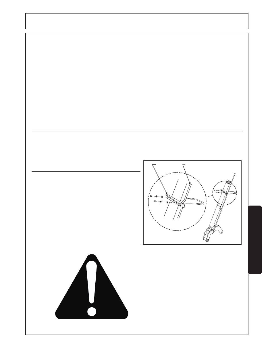
ADJUSTING ATTACHMENT LEVEL INDICATOR
With various tractor tire options or attachments, it may be
necessary to adjust attachment level indicator bracket up
or down tilt cylinder tube. Tractor must be on level surface
with attachment flat on surface. Loosen u-bolt to adjust.
Offset on bucket level indicator rod should be at slotted
hole when attachment is level.
MAINTENANCE
REPLACING WEAR BUSHINGS
Loader lift and tilt cylinders are manufactured with
replaceable wear bushings at each end. (Refer to
cylinder illustrations on previous pages.) Wear bushings
are designed to be easily replaced using tools ordinarily
available.
1. Use a drift pin to remove wear bushing.
2. Press replacement bushing in place using mallet and
block of wood, or similar method.
F-3778-12-04
Maintenance Section 5-5
Level indicator
bracket
Level Indicator
Rod
THIS SAFETY SYMBOL MEANS
ATTENTION!
BECOME ALERT!
YOUR SAFETY IS
INVOLVED!