Tilt cylinder service -4, Maintenance – Alamo RHINO 7214 MSL User Manual
Page 37
© 2004 Alamo Group Inc.
MAINTENANCE
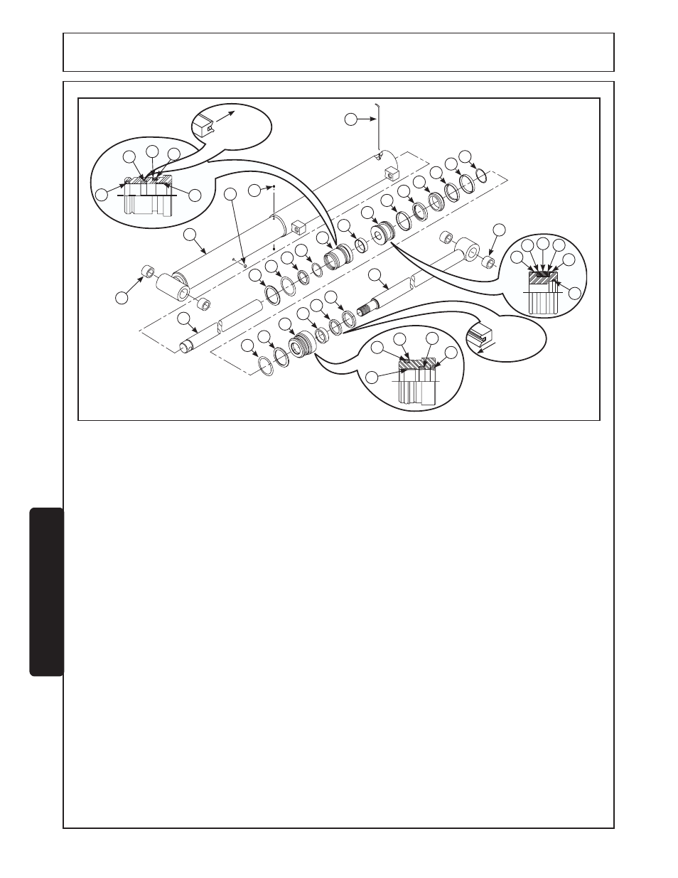
TILT CYLINDER DISASSEMBLY
1. Remove cylinder from loader.
2. Secure cylinder in a vise and manually extend and
retract cylinder rod to remove oil in cylinder.
3. With cylinder rod fully extended, remove set screws
(21) from cylinder. Remove plug (20) and apply air
pressure into hole where plug was removed. This will
unseat internal head (8) and move it along cylinder
rod.
4. Hold cylinder tube (1) stationary and pull retaining wire
(2) out through slot while turning head (17) in same
direction.
5. Pull shaft (19) with all assembled parts out of cylinder
tube (1).
6. Remove internal head (8) from cylinder shaft.
7. To remove piston from rod assembly, hold shaft
assembly by placing a rod through hole in shaft (3) and
a shaft through cross head shaft (19) and turn
counterclockwise.
8. Remove wiper seal (6), rod seal (7), and wear ring (9)
from inside cylinder head (8), and backup ring (4) and
o-ring (5) from groove on outside of head (17).
9. Remove wiper seal (18), rod seal (7), and wear ring (9)
from inside cylinder head (17), and o-ring (15) with
backup ring (16) from groove on outside of head (17).
10.Remove piston wear rings (11), support rings (12), and
seal (13) from outside groove of piston (10).
11.Clean all parts, including cylinder tube, in suitable
cleaning solvent, then use air pressure to blow away
any dirt or excess solvent from all parts.
12.Examine all parts for wear or damage and replace, if
necessary.
TILT CYLINDER REASSEMBLY
NOTE: Be careful not to damage seals and o-rings on
edges or holes in cylinder tube. Inspect and remove burrs
and sharp edges if necessary before reassembly.
1. Place rod seal (7) into groove inside cylinder heads (8
& 17).
NOTE: Lips of seal (7) must face pressure side of
cylinder as shown in cutout illustrations of head
assemblies and seal must be firmly seated in grooves.
2. Install wiper seal (6) with lip of seal facing out into
groove on cylinder head (8).
3. Install wiper seal (18) with lip facing out and flush with
top of cylinder head (17).
4. Install wear ring (9) inside other end of cylinder heads
(8 & 17).
5. Place backup ring (16) and o-ring (15) in groove on
outside of head (17). Make sure o-ring and backup ring
are installed as shown in cutout illustration for head
(17).
MAINTENANCE
1
20
22
23
21
2
3
15
16
17
9
7
18
9
15
16
7
18
19
4
5
6
7
8
9
10
11
12
13
12
11
14
6
7
4
5
9
11
12
13
12
11
14
Lips of seal
(7) must face
inward.
Lips of seal
(7) must face
inward.
F-3778-12-04
Maintenance Section 5-4
TILT CYLINDER