Drain connection – Alliance Laundry Systems CFD16C User Manual
Page 24
© Copyright, Alliance Laundry Systems LLC – DO NOT COPY or TRANSMIT
Installation
9001909
22
Drain Connection
A drain system of adequate capacity is essential to
washer-extractor performance.
Ideally, the water should empty through a vented pipe
directly into a sump or floor drain.
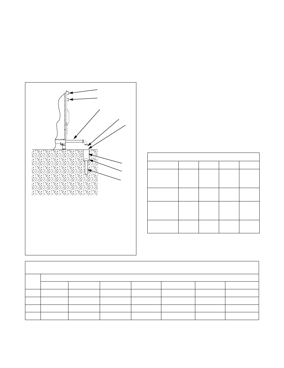
Figure 15 shows drain line and drain trough
configurations.
Figure 15
A flexible connection must be made to a vented or air
gap drain system to prevent an air lock and to prevent
siphoning. If proper drain size is not available or
practical, a surge tank is required. A surge tank in
conjunction with a sump pump should be used when
gravity drainage is not possible, such as in below-
ground-level installations.
Before any deviation from specified installation
procedures is attempted, the customer or installer
should contact the distributor.
Increasing the drain hose length, installing elbows, or
causing bends will decrease, impairing washer-
extractor performance.
Refer to Table 3 for capacity-specific drain
information.
Installation of additional washer-extractors will
require proportionately larger drain connections. Refer
to Table 4.
CFS490N
1
Water Inlet
2
Water Inlet Air Gap
3
Drain Pipe
4
1 in. minimum Waste Line Air Gap
(if required)
5
Steel Grate
6
Drain Trough (if required)
7
Strainer (if required)
8
Waste Line
REAR OF MACHINE
3
5
6
1
7
8
2
4
Drain Information
Model
18
30
33
40
Drain
connection
size, ID
2 in.
(51 mm)
2 in.
(51 mm)
2 in.
(50 mm)
2 in.
(50 mm)
Number of
drain outlets
1
1
1
1
Drain flow
capacity
20 gal/
min
(76 l/min)
20 gal/
min
(76 l/min)
21.13 gal/
min
(80 l/min)
21.13 gal/
min
(80 l/min)
Recommended
drain pit size
1.8 ft
3
(51 l)
2.5 ft
3
(70.3 l)
5.1 ft
3
(145 l)
6.4 ft
3
(181 l)
Table 3
Drain Line Sizing
Minimum Drain ID
Model
Number of Machines
1
2
3
4
5
6
7
18
2 in. (51 mm) 3 in. (76.2 mm)
3 in. (76 mm) 4 in. (102 mm) 4 in. (102 mm) 5 in. (124 mm) 5.5 in.(140 mm)
30
2 in. (51 mm) 3 in. (76.2 mm) 3.5 in. (88 mm) 4 in. (102 mm) 4.5 in. (114 mm) 5 in. (124 mm) 5.5 in. (140 mm)
33
2 in. (51 mm) 3 in. (76.2 mm) 3.5 in. (88 mm) 4 in. (102 mm) 4.5 in. (114 mm) 5 in. (124 mm) 5.5 in. (140 mm)
40
2 in. (51 mm) 3 in. (76.2 mm) 3.5 in. (88 mm) 4 in. (102 mm) 4.5 in. (114 mm) 5 in. (124 mm) 5.5 in. (140 mm)
Table 4