Receiver connections and installation – Spektrum SPM20310 DX3.0 User Manual
Page 11
11
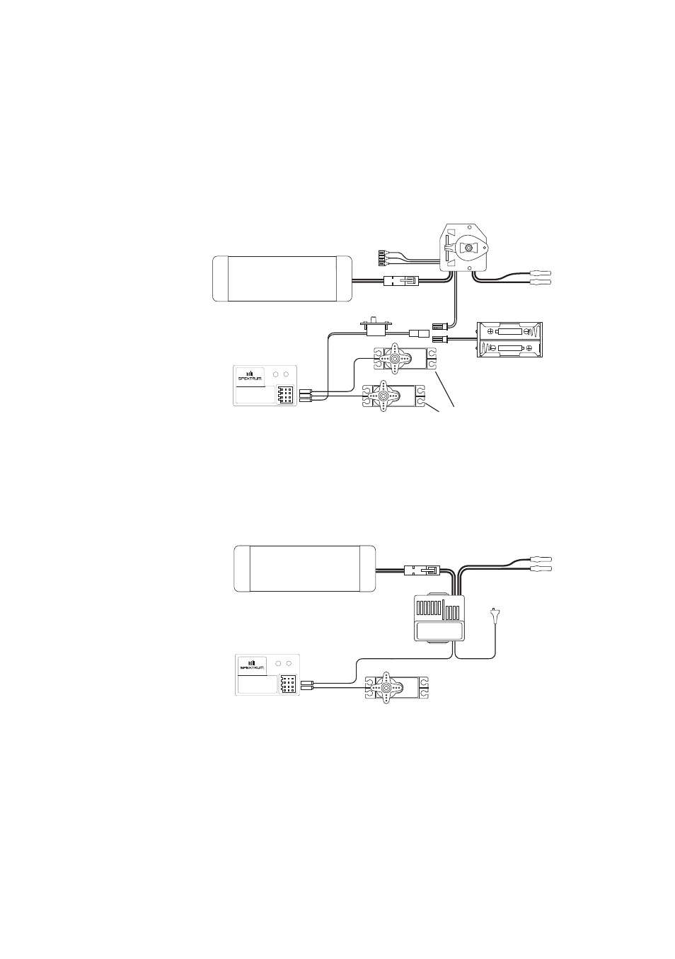
Note: When using a separate Ni-Cd receiver battery as a power source, the operating
voltage range is 4.8–6.0V (4–5 cells) underload.
Attention: Make sure the male and female connectors have the correct polarity (+/–)
before connecting. Be sure to orient the servo plug correctly for proper insertion.
Most electronic speed controllers are set up for Battery Eliminator Circuit (B.E.C.) operation
and plug directly into your receiver. See Figure A for a typical setup and check your speed
controller’s manual for correct installation.
7#BUUFSZ
5P3FTJTUPST
.FDIBOJDBM
4QFFE$POUSPM
#BUUFSZ#PY
'PSVTFXJUIPQUJPOBM
TFQBSBUFSFDFJWFSCBUUFSZQPXFS
3FDFJWFS
4XJUDI
#&$
$POOFDUPS
4FSWPT
43
"69
5)3
3Y
453
#"55&-
%4.(I[
463'"$&64&0/-:
ª)PSJ[PO)PCCZ *OD
Figure A – Connections to B.E.C. and receiver with mechanical speed controller. Ni-Cd
battery and speed controller are not included in the radio set.
7#BUUFSZ
5P.PUPS
&MFDUSPOJD
4QFFE$POUSPM
3FDFJWFS
4FSWP
43
"69
5)3
3Y
453
#"55&-
%4.(I[
463'"$&64&0/-:
ª)PSJ[PO)PCCZ *OD
Figure B – Connections to B.E.C. and receiver with electronic speed controller. Ni-Cd
battery and speed controller are not included in the radio set.
Receiver
Connections
and
Installation