Rj-45 twisted pair port pinouts, Table 9, Table 10 – Allied Telesis AT-8088/xx (MT and SC) User Manual
Page 84
Technical Specifications
84
RJ-45 Twisted Pair Port Pinouts
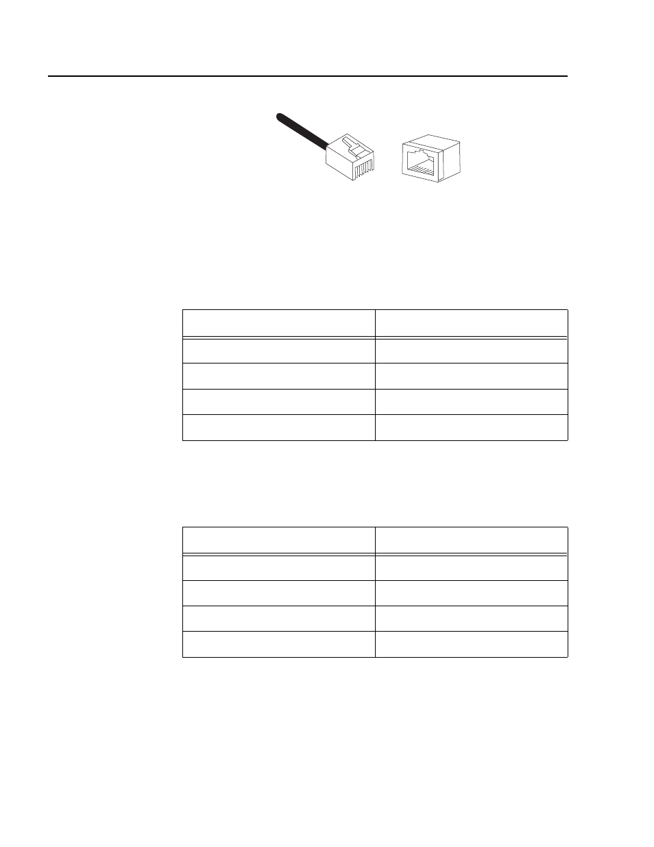
Figure 39 illustrates the pin layout to an RJ-45 connector and port.
Figure 39 RJ-45 Connector and Port Pin Layout
Table 9 lists the RJ-45 pin signals when a twisted pair port is operating in
the MDI configuration at 10 or 100 Mbps.
Table 10 lists the RJ-45 port pin signals when a twisted pair port is
operating in the MDI-X configuration at 10 or 100 Mbps.
Table 9 MDI Pin Signals (10/100Base-TX)
Pin
Signal
1
TX+
2
TX-
3
RX+
6
RX-
Table 10 MDI-X Pin Signals (10/100Base-TX)
Pin
Signal
1
RX+
2
RX-
3
TX+
6
TX-
8
8
1
1