Allied Telesis AT-MCF112VF, SM, LH User Manual
Page 22
12
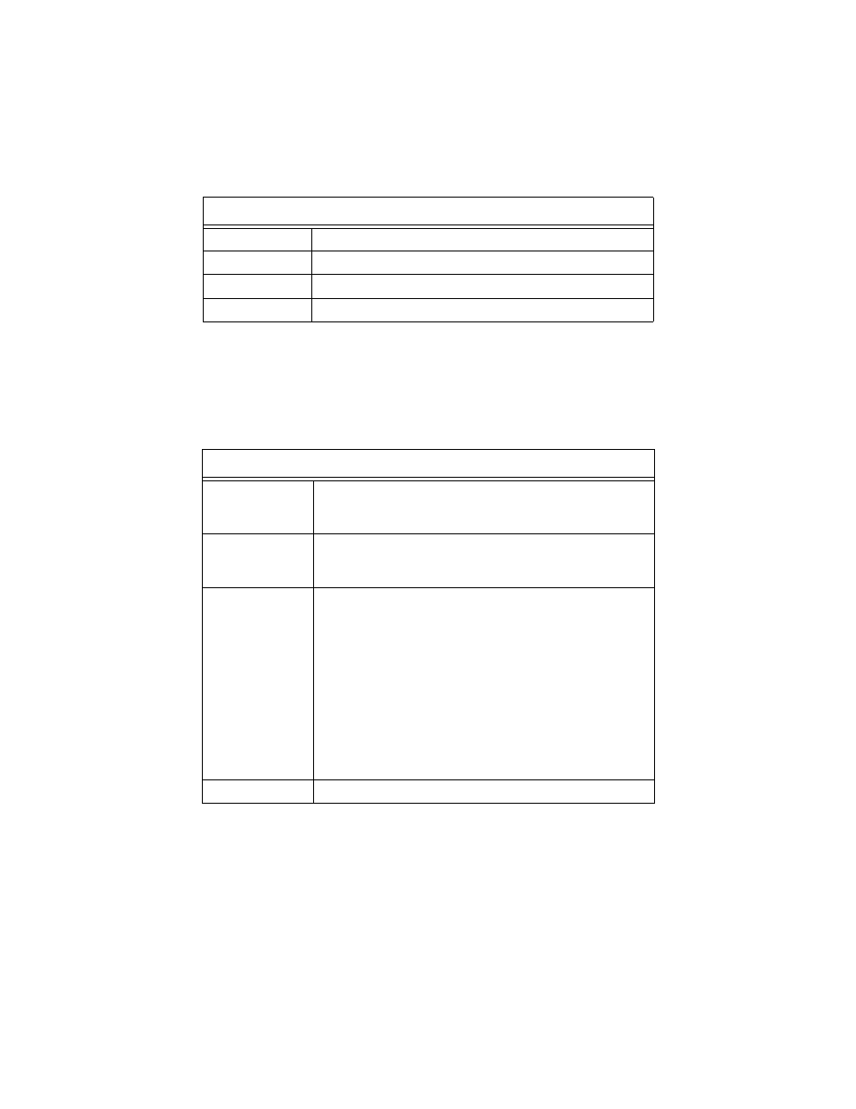
Table 2 Twisted Pair Cabling Specifications
"
Use a straight-through cable to connect a hub or switch to a twisted
pair port on the unit. Use a crossover cable to connect a workstation to
a twisted pair port on the unit.
"
Refer to Table 3 for the fiber optic cabling specifications.
Table 3 Fiber Optic Cabling Specifications
Specifications
Type
Shielded or unshielded twisted pair
Cable category
5 or better
Maximum distance
100 m (328 ft)
External device
Network adapter card, repeater, switch, router, or hub
Specifications
Media
50/125 micron multimode fiber (MMF)
62.5/125 micron multimode fiber (MMF)
9/125 micron single-mode fiber
1
(SMF)
1. The single-mode fiber optic transmitter is rated as a Class 1 laser.
Maximum Segment
Length - Full-duplex
Multi-mode fiber: 2 km (1.24 mi)
Single mode fiber: 15 km (9.3 mi)
2
Single mode fiber: 40 km (24.8 mi)
3
2. This applies to the AT-MCF106SM and AT-MCF112SM models only.
3. This applies to the AT-MCF106LH and AT-MCF112LH models only.
Maximum Segment
Length - Half-duplex
The total distance of all fiber runs cannot exceed the following limits:
4
With one Media Converter inline:
Switch to Switch = 372 m (1221 ft)
Workstation to Switch = 372 m (1221 ft)
Switch to Class II Repeater = 185 m (607 ft)
Switch to Class I Repeater = 137 m (450 ft)
With two Media Converters inline:
Switch to Switch = 332 m (1089 ft)
Workstation to Switch = 332 m (1089 ft)
Switch to Class II Repeater =145 m (476 ft)
Switch to Class I Repeater = 97 m (318 ft)
4. Each media converter used inline within a single collision domain will reduce the overall
segment length by 40 m (131.24 ft) of fiber.
External Devices
Network Adapter Card, Repeater, Switch, or Router