Pinout assignments – Allied Telesis AT-MC14 User Manual
Page 31
AT-MC13 and AT-MC14 Installation Guide
21
Table 9 Fiber Optic Loss Specification (Benchmarks)
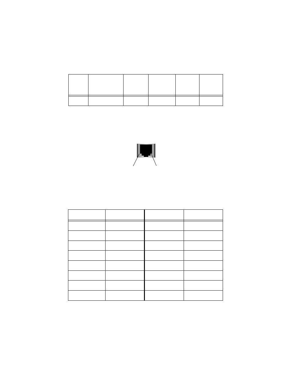
Pinout Assignments
Figure 6 shows the pin assignments of the RJ-45 connector.
Figure 6 RJ-45 Pin Assignments
Table 10 lists the 10Base-T connector pins and their signals when the port is
operating in either MDI or MDI-X configuration.
Table 10 RJ-45 Pin Signals
Fiber
Type
1
1. MMF = Multimode Fiber.
Fiber Optic
Diameter
Optical
Frequency
Typical Loss
Factor
Worst Case
Loss
Factor
Bandwidth
MMF
62.5/125 microns
850 nm
3.00 dB/km
3.75 dB/km
200
MDI-X (Default)
Signal
MDI
Signal
1
RX+
1
TX+
2
RX-
2
TX-
3
TX+
3
RX+
4
-
4
-
5
-
5
-
6
TX-
6
RX-
7
-
7
-
8
-
8
-
Pin 1
Pin 8
This manual is related to the following products:
See also other documents in the category Allied Telesis Computer hardware:
- AT-GS908M (54 pages)
- AT-x230-10GP (80 pages)
- AT-GS950/48PS (64 pages)
- AT-GS950/10PS (386 pages)
- AT-GS950/16PS (386 pages)
- AT-GS950/48PS (386 pages)
- AT-9000 Series (258 pages)
- AT-9000 Series (1480 pages)
- IE200 Series (70 pages)
- AT-GS950/48 (378 pages)
- AT-GS950/48 (60 pages)
- AT-GS950/48 (410 pages)
- AT-GS950/8 (52 pages)
- SwitchBlade x8106 (322 pages)
- SwitchBlade x8112 (322 pages)
- SwitchBlade x8106 (240 pages)
- SwitchBlade x8112 (240 pages)
- AT-TQ Series (172 pages)
- AlliedWare Plus Operating System Version 5.4.4C (x310-26FT,x310-26FP,x310-50FT,x310-50FP) (2220 pages)
- FS970M Series (106 pages)
- 8100S Series (140 pages)
- 8100L Series (116 pages)
- x310 Series (116 pages)
- x310 Series (120 pages)
- AT-GS950/16 (44 pages)
- AT-GS950/24 (404 pages)
- AT-GS950/24 (366 pages)
- AT-GS950/16 (404 pages)
- AT-GS950/16 (364 pages)
- AT-GS950/8 (404 pages)
- AT-GS950/8 (364 pages)
- AT-GS950/8 (52 pages)
- AT-8100 Series (330 pages)
- AT-8100 Series (1962 pages)
- AT-FS970M Series (330 pages)
- AT-FS970M Series (1938 pages)
- SwitchBlade x3106 (288 pages)
- SwitchBlade x3112 (294 pages)
- SwitchBlade x3106 (260 pages)
- SwitchBlade x3112 (222 pages)
- AT-S95 CLI (AT-8000GS Series) (397 pages)
- AT-S94 CLI (AT-8000S Series) (402 pages)
- AT-IMC1000T/SFP (23 pages)
- AT-IMC1000TP/SFP (24 pages)
- AT-SBx3106WMB (44 pages)