Multimode port specifications (all models) – Allied Telesis AT-MC104ST/FS3, FS4 User Manual
Page 26
16
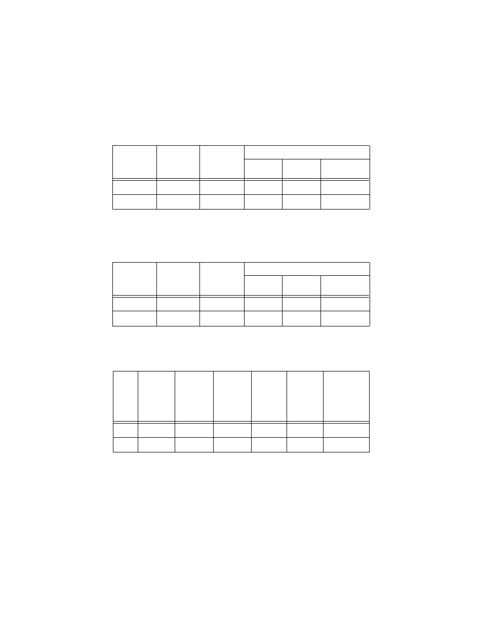
Multimode Port Specifications (All Models)
Table 10 Fiber Optic Transmitter
Table 11 Fiber Optic Receiver
Table 12 Fiber Optic Datalink
Fiber Type
1
1. MMF = Multimode Fiber
Fiber Optic
Diameter
(microns)
Optical
Frequency
Launch Power (dBm)
2
2. Launch power measured at one meter from the transmitter.
Maximum
Average
Minimum
MMF
50/125 1310
nm
-14.0
-20.3
-22.5
MMF
62.5/125
1310 nm
-14.0
-16.8
-19.0
Fiber Type
1
1. MMF = Multimode Fiber
Fiber Optic
Diameter
(microns)
Optical
Frequency
Receive Power (dBm)
Minimum
Typical
Saturation
MMF
50/125
1310 nm
-31.8
-34.5
-14.0
MMF
62.5/125
1310 nm
-31.8
-34.5
-14.0
Fiber
Type
1
1. MMF = Multimode Fiber
Fiber
Optic
Diameter
(microns)
Optical
Frequency
Minimum
Power/
Link
Budget
(dB)
Average
Signal
Loss (dB)
Minimum
Distance
Specs
2
2. In all cases where the maximum transmitter output power exceeds the receivers sensitivity, a recommended
minimum ranges is stated. This is to prevent blinding or burning out the optical receiver on the far-end
node.
Maximum
Distance
Specs
(Full-duplex
only)
MMF
50/125
1310 nm
13.00
18.70
0
2 km (1.2 mi)
MMF
62.5/125
1310 nm
16.80
22.50
0
2 km (1.2 mi)