Installing the media converter – Allied Telesis AT-MC104ST/FS3, FS4 User Manual
Page 20
10
Installing the Media Converter
The following procedure explains how to install the media converter.
If you are building a back-to-back installation, please review the following. See
Figure 3 for an illustration of a back-to-back-media converter configuration.
❑
During installation, setup, and testing of back-to-back media
converters, make sure each media converters Link Test/MissingLink
button is in the LNK TST (OUT) position.
❑
When two media converters are connected back-to-back with no UTP/
STP cables connected and when the LNK TST button is in the OUT
position (link test mode), the ACT LEDs on each converter may flash.
This is normal and will not affect the normal operation of the
converters.
To install the unit, perform the following procedure:
1.
Remove all equipment from the package and store the packaging material
in a safe place.
2.
If you are installing the unit on a desktop, attach the four rubber feet to
the base of the unit, placing one rubber foot in each corner. If you are
installing the unit in an AT-MCR12 chassis or AT-TRAY4 tray, do not
attach the rubber feet.
3.
Set the Link Test/MissingLink button to LNK TST (OUT) position.
4.
If you are installing the unit in an AT-MCR12 chassis or AT-TRAY4 tray,
refer to the appropriate installation guide for instructions on how to
install the media converter into the unit.
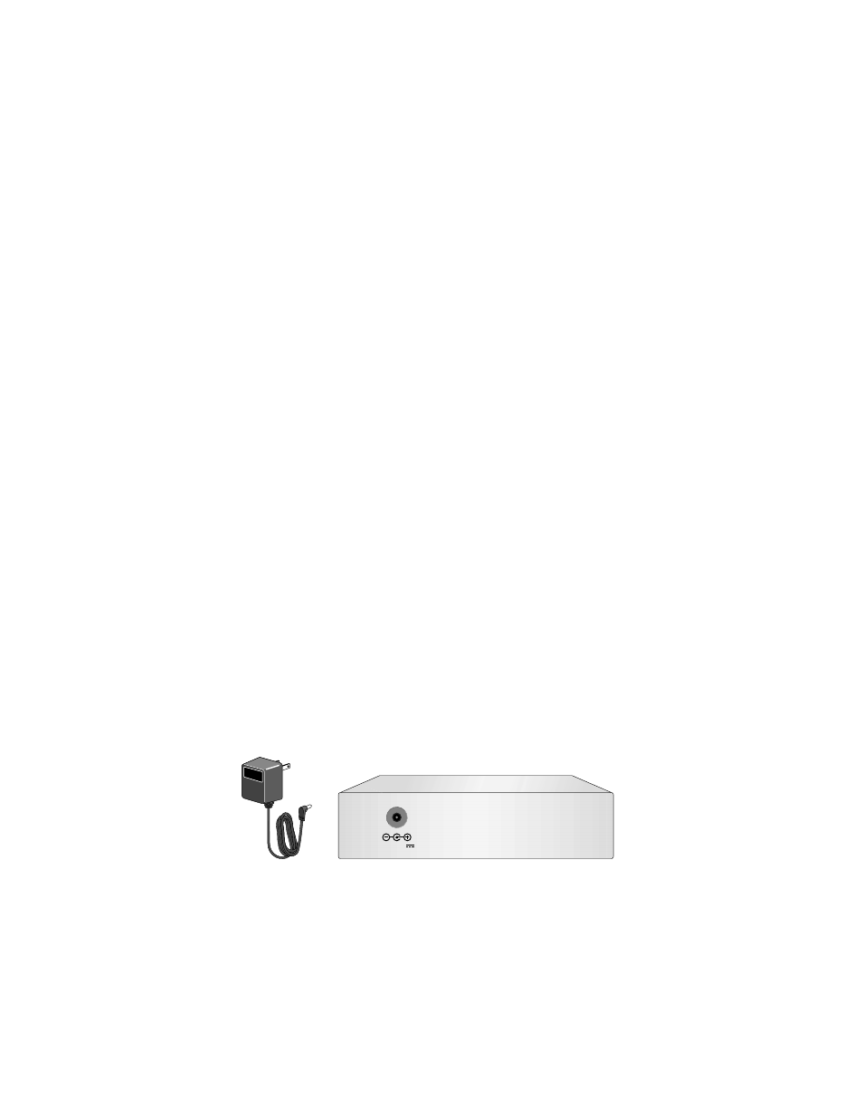
5.
Plug the AC/DC power adapter into an appropriate AC power outlet and
inset the power plug into the DC receptacle located on the rear panel.
(This step does not apply if you installed the unit in an AT-MCR12
chassis.)
Figure 4 12V DC Connector on Rear Panel with External Power Adapter
6.
Verify that the Power LED is green.
12 V D C