Key features – Allied Telesis AT-MC104ST/FS3, FS4 User Manual
Page 12
2
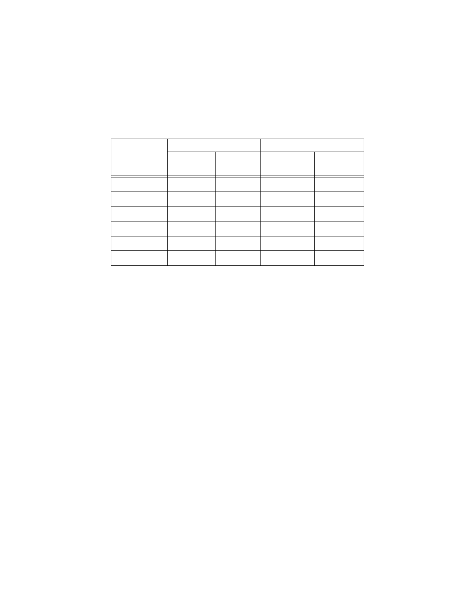
Table 1 list the maximum cabling distances for each model.
Table 1 Maximum Operating Distances
Key Features
The media converters have the following key features:
❑
LEDs for unit and port status
❑
Two 100Base-FX fiber optic ports
❑
Link Test/MissingLink
button for performing a link test on the fiber
ports and notifies node of connection failures
❑
Half- or full-duplex operation
❑
External AC/DC power adapter
❑
Standard size for use with an AT-MCR12 chassis or AT-TRAY4 tray
Model
Type of Connector
Maximum Distance
1
1. Maximum distance may be less depending on the duplex mode of the end stations and the type of fiber optic
cabling used with the port.
Port 1
(Single-mode)
Port 2
(Multimode)
Port 1
(Single-mode)
Port 2
(Multimode)
AT-MC104XL
SC
SC
15 km (9.3 mi)
2 km (1.2 mi)
AT-MC104LH
SC
SC
40 km (24.8 mi)
2 km (1.2 mi)
AT-MC104SC/FS3 SC
SC
75 km (46.5 mi)
2 km (1.2 mi)
AT-MC104ST/FS3
ST
ST
75 km (46.5 mi)
2 km (1.2 mi)
AT-MC104SC/FS4 SC
SC
100 km (62 mi)
2 km (1.2 mi)
AT-MC104ST/FS4
ST
ST
100 km (62 mi)
2 km (1.2 mi)