Attach the two brackets, one to each opposite c, Connect one end of the db-15 proprietary cable, Attach the power adapter dc jacks to the hubs a – Allied Telesis AT-MR904TX User Manual
Page 19: At-mr904tx hub 9
AT-MR904TX Hub
9
5.
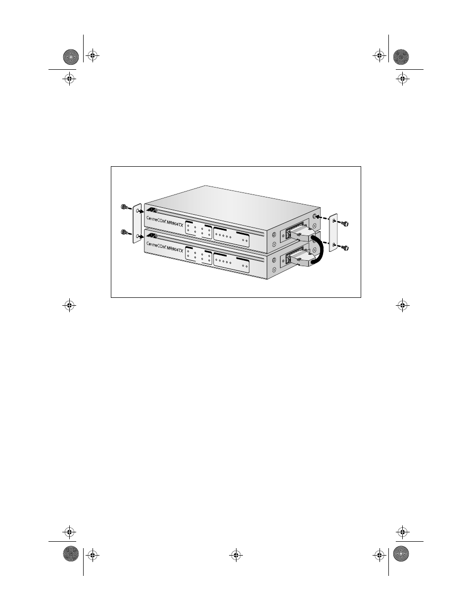
Attach the two brackets, one to each opposite corner of the unit, as
6.
Connect one end of the DB-15 proprietary cable to the first hub’s AUI
port. Connect the other end of the cable to the AUI port of the second
hub. Make sure that the DB-15 proprietary cable is securely
connected.
Figure 7: Attaching Brackets and Connecting DB-15 Proprietary Cable
7.
Attach the power adapter DC jacks to the hubs and connect them to the
AC outlets.
100BASE-TX IEEE 802.3u 4 PORT ST
ACKABLE HUB
LINK /
ACTIVITY
ERROR
HUB ST
ATUS
1
2
3
4
1
8
16
32
64
Utilization
(%)
COL PWR
100BASE-TX IEEE 802.3u 4 PORT ST
ACKABLE HUB
LINK /
ACTIVITY
ERROR
HUB ST
ATUS
1
2
3
4
1
8
16
32
64
Utilization
(%)
COL PWR
MR904C1Book Page 9 Tuesday, September 2, 1997 10:28 AM
See also other documents in the category Allied Telesis Computer hardware:
- AT-GS908M (54 pages)
- AT-x230-10GP (80 pages)
- AT-GS950/48PS (64 pages)
- AT-GS950/10PS (386 pages)
- AT-GS950/16PS (386 pages)
- AT-GS950/48PS (386 pages)
- AT-9000 Series (258 pages)
- AT-9000 Series (1480 pages)
- IE200 Series (70 pages)
- AT-GS950/48 (60 pages)
- AT-GS950/48 (410 pages)
- AT-GS950/8 (52 pages)
- AT-GS950/48 (378 pages)
- SwitchBlade x8106 (322 pages)
- SwitchBlade x8112 (322 pages)
- SwitchBlade x8106 (240 pages)
- SwitchBlade x8112 (240 pages)
- AT-TQ Series (172 pages)
- AlliedWare Plus Operating System Version 5.4.4C (x310-26FT,x310-26FP,x310-50FT,x310-50FP) (2220 pages)
- FS970M Series (106 pages)
- 8100L Series (116 pages)
- 8100S Series (140 pages)
- x310 Series (116 pages)
- x310 Series (120 pages)
- AT-GS950/24 (404 pages)
- AT-GS950/24 (366 pages)
- AT-GS950/16 (44 pages)
- AT-GS950/16 (404 pages)
- AT-GS950/16 (364 pages)
- AT-GS950/8 (52 pages)
- AT-GS950/8 (404 pages)
- AT-GS950/8 (364 pages)
- AT-8100 Series (330 pages)
- AT-8100 Series (1962 pages)
- AT-FS970M Series (330 pages)
- AT-FS970M Series (1938 pages)
- SwitchBlade x3112 (294 pages)
- SwitchBlade x3106 (288 pages)
- SwitchBlade x3106 (260 pages)
- SwitchBlade x3112 (222 pages)
- AT-S95 CLI (AT-8000GS Series) (397 pages)
- AT-S94 CLI (AT-8000S Series) (402 pages)
- AT-IMC1000T/SFP (23 pages)
- AT-IMC1000TP/SFP (24 pages)
- AT-SBx3106WMB (44 pages)