Rear panel description, Uplink port, Dc power socket – Allied Telesis AT-MR904TX User Manual
Page 14: Stack id switch, Cabling requirements
4
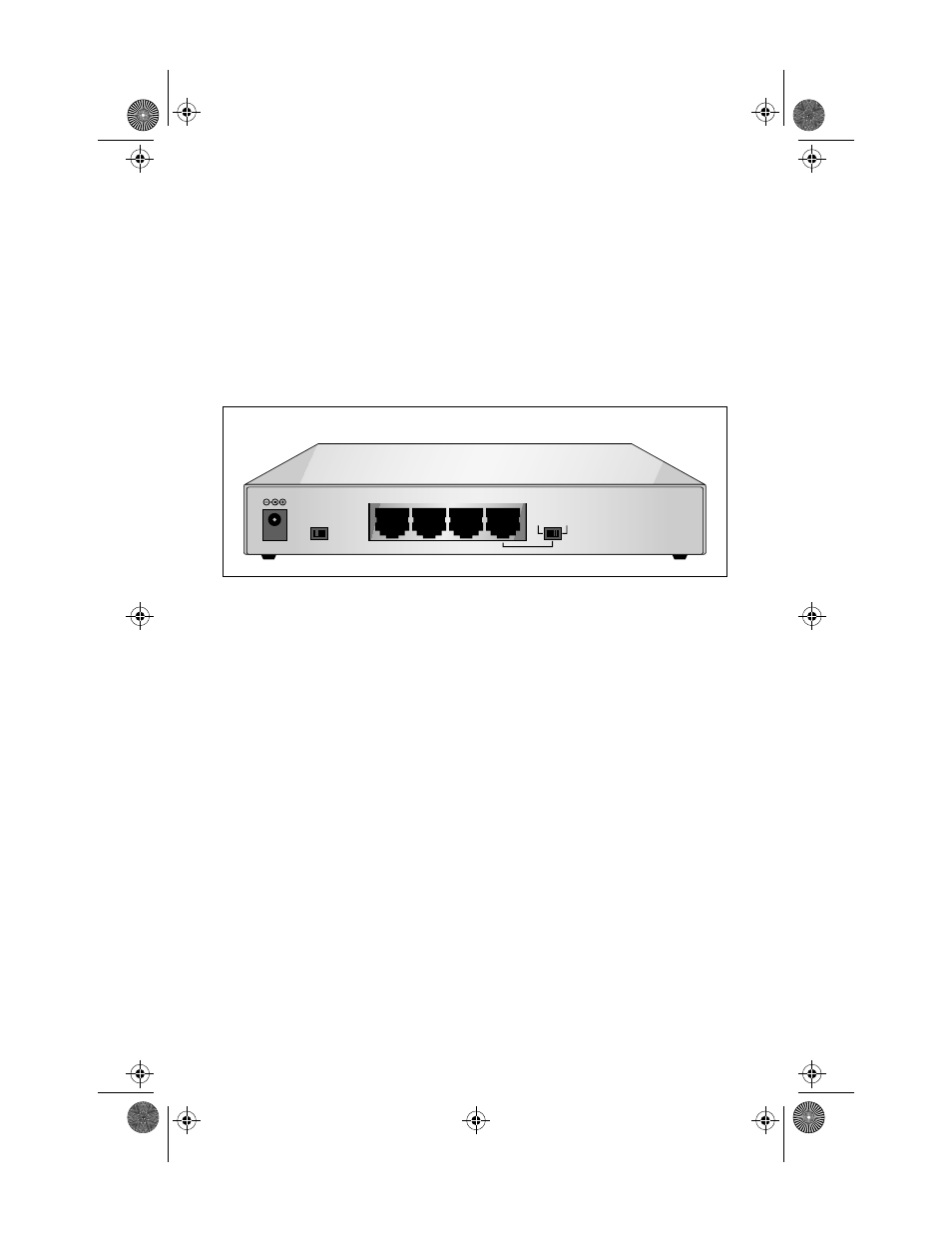
Rear Panel Description
The rear panel consists of the following components:
❑
DC power socket
❑
Four shielded RJ45 connectors
❑
Uplink MDI/MDI-X slide switch
❑
Stack ID switch
Figure 3: Rear Panel
Uplink Port. You can use any of the shielded RJ45 connectors to connect to a
100Base-TX node using Category 5 S/UTP cabling. The uplink port provides
cascading capabilities to a second AT-MR904TX 100Base-TX Fast Ethernet
hub.
DC Power Socket. The DC power socket accepts DC power input from a
+12V power adapter. The 4-port hub includes an internal switching power
supply and can accept a wide range DC power input which offers more
reliability.
STACK ID Switch. Set the STACK ID switch to 1 for the first Base hub. Set
the second stackable hub switch to 2.
Cabling Requirements
To operate your network reliably at 100Mbps, you must use Category 5 S/UTP
or higher data grade wire, with a 100 meter maximum length.
+9
~
12VDC
STACK ID
MDI-X
4X
3X
2X
1
MDI
1
2
MR904C1Book Page 4 Tuesday, September 2, 1997 10:28 AM