Installing stackable hubs, Make sure that all of the unit’s power is turne, Place the hubs on a flat surface – Allied Telesis AT-MR904TX User Manual
Page 18: For the first base hub, set the stack id switch, Remove the two bracket screws from the right si
8
Installing Stackable Hubs
This hub can use the stackable port (AUI) and Uplink for extension port
numbers. As your network grows, the stackable and uplink feature allows you
to use two stacked pairs for expansion of up to 14 ports on the Class I and Class
II repeater standards.
To install stackable hubs, do the following:
1.
Make sure that all of the unit’s power is turned off.
2.
Place the hubs on a flat surface.
Note
Make sure that the cable length between hub and desktop does not
exceed 100 meters (328 ft.) and that Category 5 UTP/STP cabling is
used.
3.
For the first base hub, set the STACK ID switch to 1 and for the second
stackable hub, set the ID switch to 2.
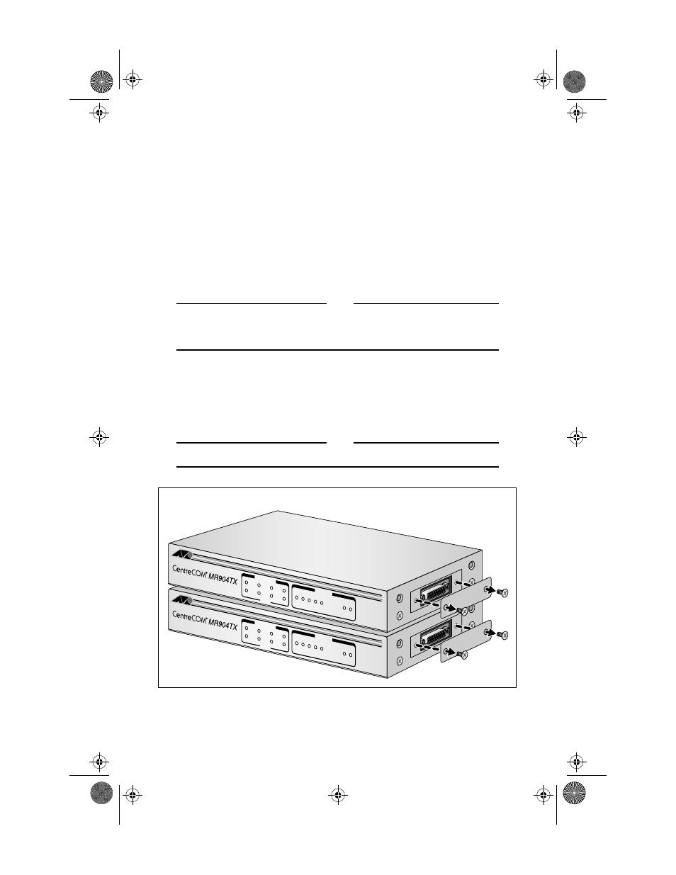
4.
Remove the two bracket screws from the right side of the hubs. See
Note
This hub is not hot swappable.
Figure 6: Removing Cover Screws
100BASE-TX IEEE 802.3u 4 PORT ST
ACKABLE HUB
LINK /
ACTIVITY
ERROR
HUB ST
ATUS
1
2
3
4
1
8
16
32
64
Utilization
(%)
COL PWR
100BASE-TX IEEE 802.3u 4 PORT ST
ACKABLE HUB
LINK /
ACTIVITY
ERROR
HUB ST
ATUS
1
2
3
4
1
8
16
32
64
Utilization
(%)
COL PWR
MR904C1Book Page 8 Tuesday, September 2, 1997 10:28 AM