Installing cascaded hubs, Connect a category 5 utp/stp cable to port 1 of, Set the mdi/mdi-x switch of port 1 on the first – Allied Telesis AT-MR904TX User Manual
Page 16: Connect the other end of the utp/stp cable to p
6
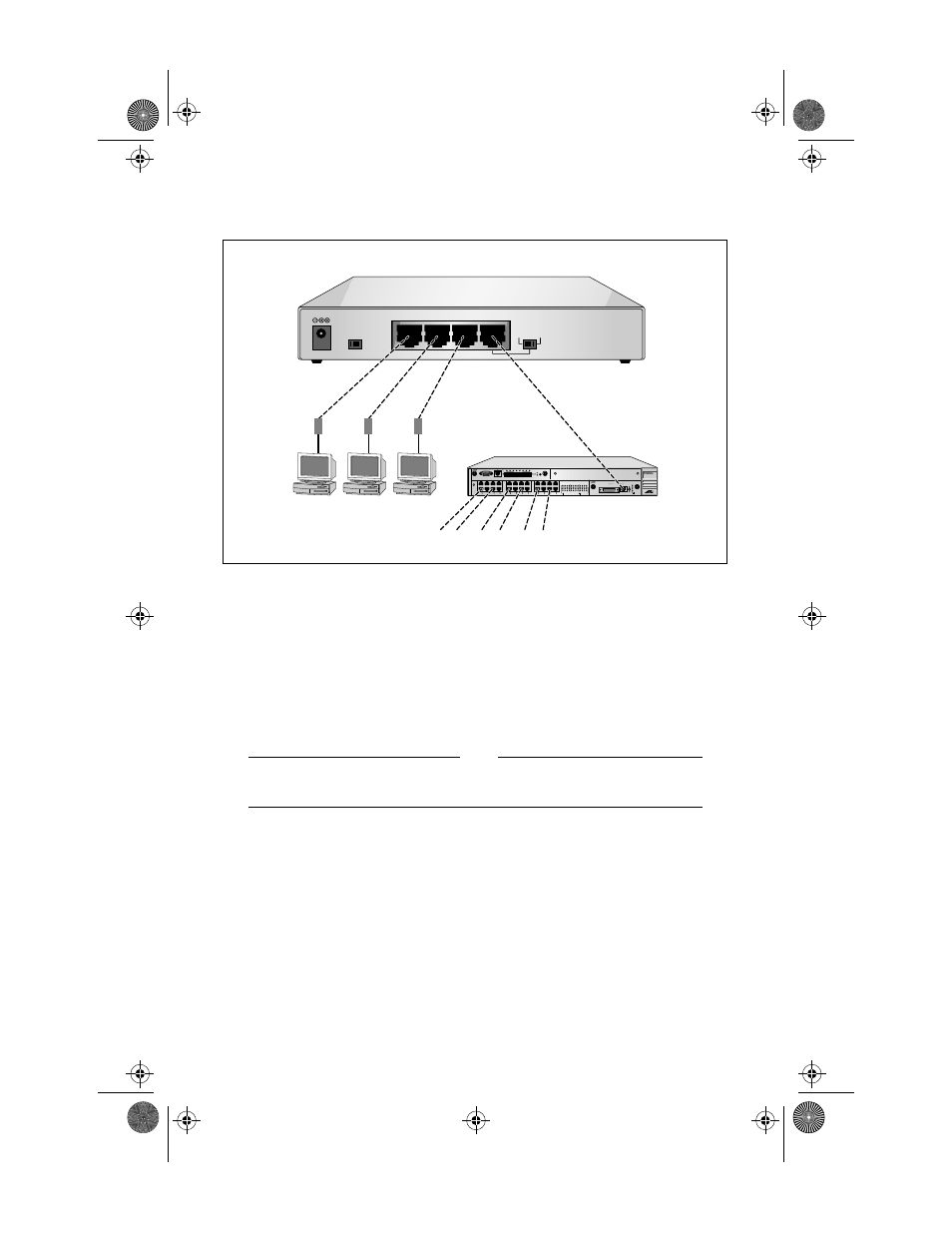
Figure 4: Standalone Configuration
Installing Cascaded Hubs
If you want to connect more than four ports, you can use the Uplink port to
connect to another hub. In compliance with IEEE 802.3u Class II repeater
specifications, two repeaters can be cascaded using a 5-meter cable in a single
collision domain.
Note
In a two-repeater configuration, a maximum of 205 meters (672 ft.) of
UTP cable is allowed (end station -to-end station).
To install cascaded hubs, do the following:
1.
Connect a Category 5 UTP/STP cable to Port 1 of the first hub.
2.
Set the MDI/MDI-X switch of Port 1 on the first hub to the MDI
position.
3.
Connect the other end of the UTP/STP cable to Port 1 through 4 of the
second hub.
100BASE-TX
M
II
PORT A
72A9
MDI
MDI-X
COLLISION
LINK OK
RX
TX
DISABLED
72MC1
RS-232 TERMINAL PORT
PORT
MIRRORING
FEATURE SLOT
NETWORK LOAD
LINK
RESET
FLT PWR
PORT M
FAN
ALARM
PS
ALARM
7224
ETHERNET SWITCH with FAST ETHERNET
1
2
3
4
5
6
7
8
9
10
11
12
13
14
15
16
17
18
19
20
21
22
23
24
GREEN - LINK OK
GREEN - RECEIVE
AMBER- DISABLED
AMBER- COLLISION
PORT ACTIVITY
10BASE-T
SWITCHED
PORTS
(MDI-X)
1
13
2
14
3
15
4
16
5
17
6
18
7
19
8
20
9
21
10
22
11
23
12
24
+9
~
12VDC
STACK ID
MDI-X
4X
3X
2X
1
MDI
1
2
Connected to other Workgroups
MR904C1Book Page 6 Tuesday, September 2, 1997 10:28 AM