Allied Telesis AT-GS924GB User Manual
Page 35
AT-GS924GB Gigabit Ethernet Switch Installation Guide
23
When attaching a fiber optic cable, observe the following
guidelines:
Ensure that the cable connector is firmly locked into place in the
port.
With a dual SC connector, ensure to connect the receiver fiber
port to the transmitter port on the remote end-node, and the
transmitter fiber port to the receiver port on the remote node.
Ensure that you are using the appropriate type of fiber optic
cabling by referring to the installation guide included with the
module.
Ensure that the operating specifications of the switch’s fiber optic
port are compatible with the fiber optic port on the remote end-
node. For example, you cannot connect a fiber optic port with a
maximum distance of 2 kilometers (1.24 miles) and an operating
wavelength of 1310 nm to another fiber optic port that has a
maximum distance of 40 kilometers (24.8 miles) and an operating
wavelength of 1550 nm.
The network should not contain data loops, which can adversely
affect network performance. A data loop exists when two or more
network devices can communicate with each other over more
than one data path.
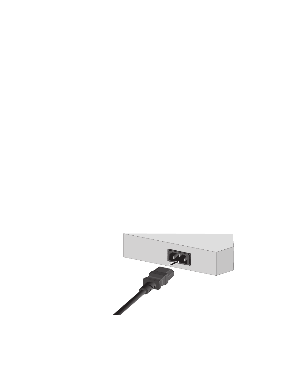
4. Apply AC power to the switch by plugging the power cord into the AC
power connector on the back panel of the unit and plugging the
other end into a wall outlet.
Figure 14 Connecting the AC Power Connector to Switch