Leds – Allied Telesis AT-GS924 User Manual
Page 13
AT-GS916 and AT-GS924 Gigabit Ethernet Switches Installation Guide
13
Auto MDI/MDI-X
All of the twisted pair ports on the switch are auto-MDI and IEEE
802.3ab-compatible. When a port's speed and duplex mode are set
through Auto-Negotiation, the port uses the auto-MDI feature to
automatically configure itself as MDI or MDI-X when connected to an
end-node. Consequently, you can use either a straight-through or
crossover twisted pair cable when connecting any network device to a
port.
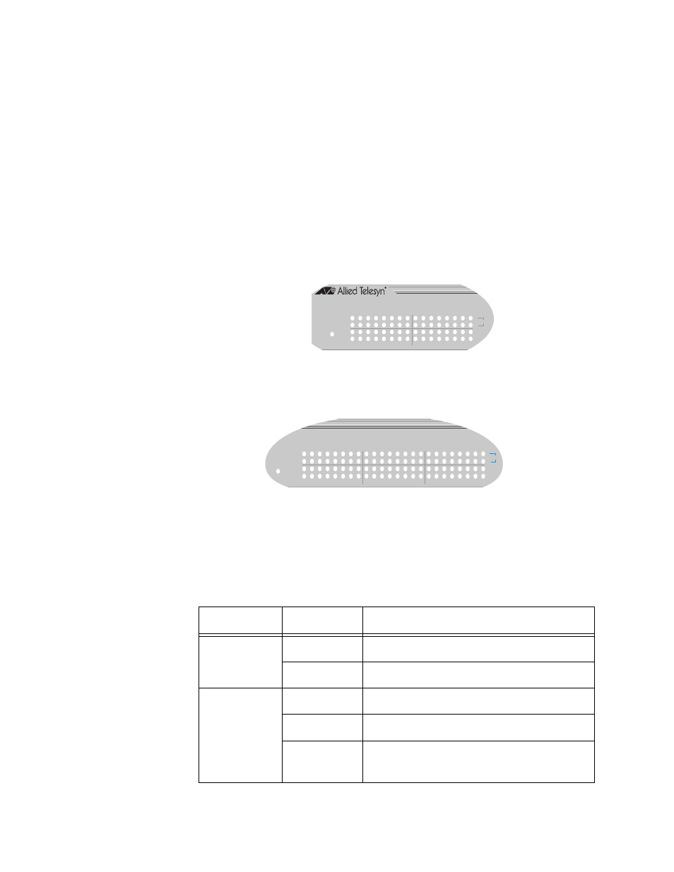
LEDs
The system and port LEDs on the front panel of the AT-GS916 and AT-
GS924 switches display the switch and its port status information. Each
port has four LEDs.
Figure 3 Port LEDs
Table 1 describes the system and port LEDs on the AT-GS916 and
AT-GS924 Gigabit Ethernet switches.
Table 1 System and Port LEDs
LED
State
Description
POWER
Green
The switch is powered ON.
OFF
The switch is powered OFF.
10
Green
The port is operating at 10 Mbps.
100
Green
The port is operating at 100 Mbps.
OFF
When both 10 and 100 LEDs are OFF,
the port is operating at 1000 Mbps.
AT-GS916
10/100/1000Base-T Gigabit Ethernet Switch
POWER
1
2
3
4
5
6
7
8
9
10
11
12
13
14
15
16
10
ACT
FDX
100
1000
POWER
10
ACT
FDX
100
1000
1
2
3
4
5
6
7
8
9
10
11
12
13
14
15
16
17
18
19
20
21
22
23
24
AT-GS916
AT-GS924