Components, System / port leds, Ac power connector – Allied Telesis AT-GS924 User Manual
Page 11
AT-GS916 and AT-GS924 Gigabit Ethernet Switches Installation Guide
11
Components
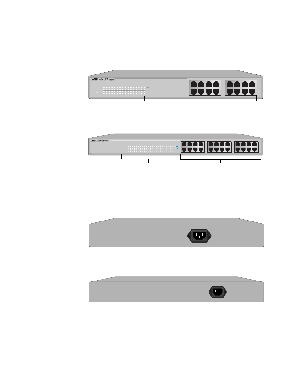
Figure 1 illustrates the front panels of the AT-GS916 and AT-GS924
switches.
Figure 1 Front Panels
Figure 1 illustrates the back panels of the AT-GS916 and AT-GS924
switches.
Figure 2 Back Panels
16 - 10/100/1000Base Twisted Pair Ports
AT-GS916
10/100/1000Base-T Gigabit Ethernet Switch
POWER
1
3
5
7
2
4
6
8
10
12
14
16
9
11
13
15
1
2
3
4
5
6
7
8
9
10
11
12
13
14
15
16
10
ACT
FDX
100
1000
System / Port LEDS
AT-GS924
10/100/1000Base-T Gigabit Ethernet Switch
POWER
10
ACT
FDX
100
1000
2
4
6
8
1
3
5
7
10
12
14
16
9
11
13
15
18
20
22
24
17
19
21
23
1
2
3
4
5
6
7
8
9
10
11
12
13
14
15
16
17
18
19
20
21
22
23
24
24 - 10/100/1000Base Twisted Pair Ports
System / Port LEDS
AT-GS916
AT-GS924
100-240VAC
~
AC Power Connector
AC Power Connector
100-240VAC
~
AT-GS916
AT-GS924
This manual is related to the following products: