Rps connector – Allied Telesis AT-8550SP User Manual
Page 36
Overview
36
RPS Connector
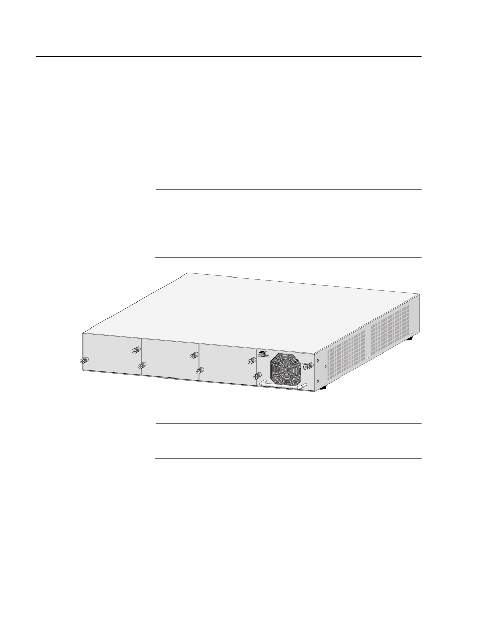
The RPS connector on the back panel of the switch connects to the
optional AT-RPS3004 redundant power supply unit, shown in Figure 7.
The unit can provide power to the switch in the event the switch’s
internal power supply should fail.
The AT-RPS3004 redundant external power supply comes with one pre-
installed AT-PWR3004 Power Module and has three empty slots for
additional power modules. Each power module can support one switch,
making the AT-RPS3004 unit capable of supporting up to four switches
simultaneously.
Note
The AT-RPS3004 unit is compatible with all AT-8500 Series switches,
except for the AT-8524POE switch. The latter uses the AT-RPS3104
unit, which was not available at the time of publication of this
document. Do not use the AT-RPS3004 unit with the AT-8524POE
switch.
Figure 7 AT-RPS3004 Redundant Power Supply Unit
Note
DC models of the AT-8500 Series switches do not feature an RPS
connector.