Allied Telesis AT-PWR3101 User Manual
Page 37
AT-RPS3104 and AT-PWR3101 Installation Guide
37
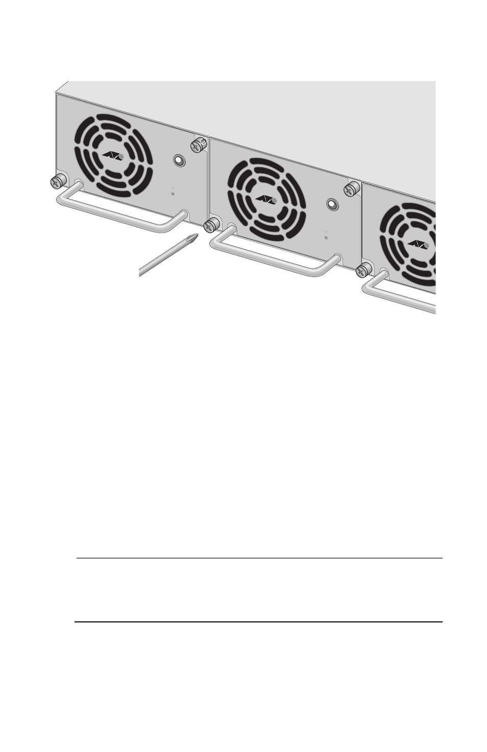
9. Using a # 1 Phillips screwdriver, tighten the two captive screws to
secure the module in the AT-RPS3104 system (see Figure 27).
Figure 27. Securing the AT-PWR3101 Module in the AT-RPS3104
System
10. Turn the slot’s corresponding On/Off power switch on the back panel
of the AT-RPS3104 system to On.
11. Check the STATUS LED on the front panel of the AT-PWR3101
module. It should be green. If the LED is off, check that all cables are
securely connected to the unit. If the LED is amber, the module has
experienced a problem. Contact your local Allied Telesyn sales
representative or Allied Telesyn technical support for assistance.
12. Check the RPS LED on the front of the AT-8524POE switch. It should
be green. If it is off, repeat this procedure to ensure that all cables are
securely connected to the switch and the RPS unit.
Note
The RPS LED on the switch is green whenever the unit detects that
an RPS unit is connected to it, even when the RPS unit is powered
off.
The installation is complete.
STATUS
AT-PWR3101
POW
ER
FAULT
STATUS
AT-PWR3101
POW
ER
FAULT