Introduction, Installation instructions 12 – Allied Telesis AT-PWR3101 User Manual
Page 12
Installation Instructions
12
Introduction
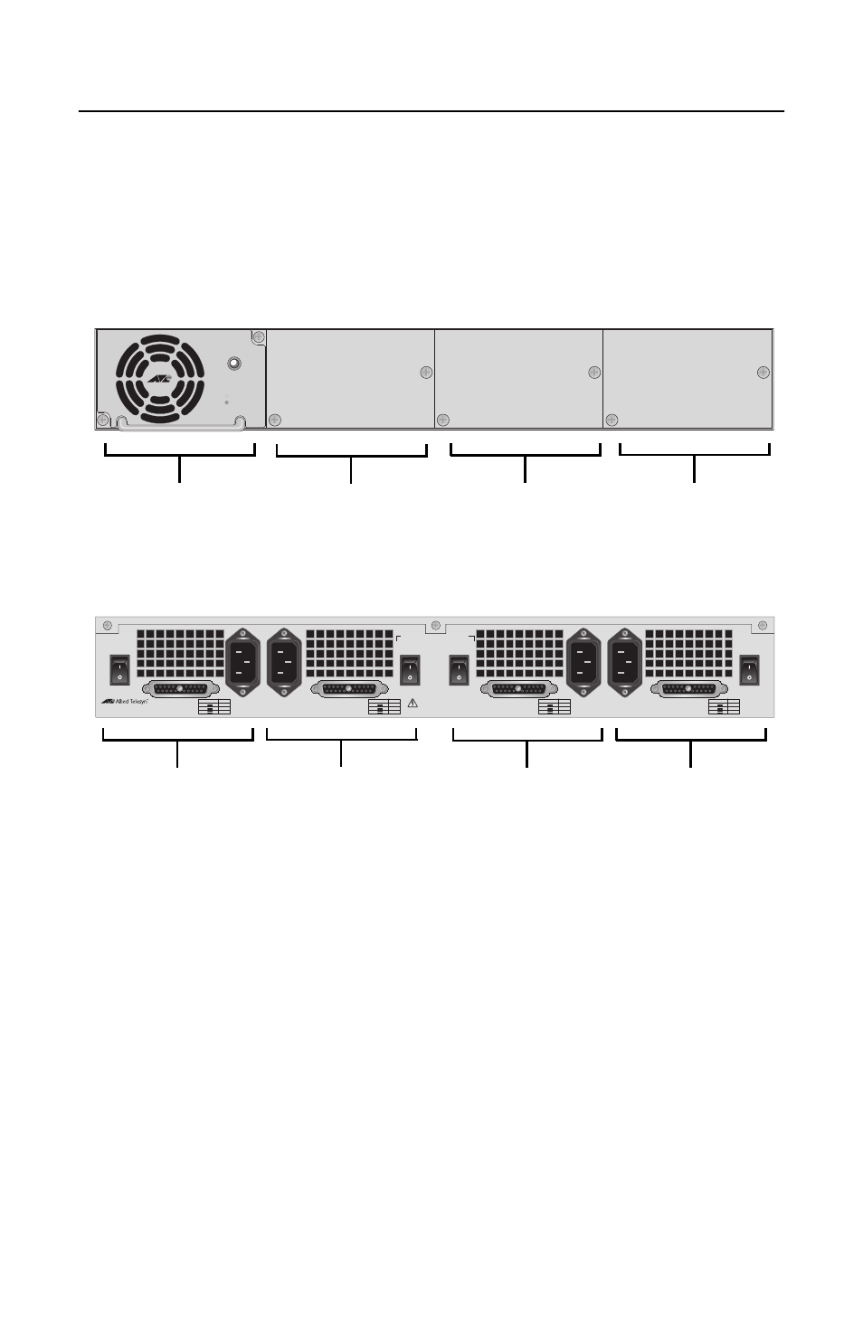
The AT-RPS3104 system comes with one pre-installed AT-PWR3101
power supply module and features three empty slots for three additional
AT-PWR3101 power supply modules. Each AT-PWR3101 module can
power one AT-8524POE switch and its powered devices. When fully
populated with AT-PWR3101 modules, the AT-RPS3104 system can
supply redundant power to up to four AT-8524POE switches.
Figure 1. AT-RPS3104 Front and Back Panels
STATUS
AT-PWR3101
POWER
FAULT
OUTPUT VDC
A MAX
+48
+12
+3.3
8.5
3
15
OUTPUT VDC
A MAX
+48
+12
+3.3
8.5
3
15
OUTPUT VDC
A MAX
+48
+12
+3.3
8.5
3
15
OUTPUT VDC
A MAX
+48
+12
+3.3
8.5
3
15
WARNING
This unit has more than one power input. To reduce the
risk of electric shock, disconnect all power inputs
before servicing unit.
ON
OFF
D
AT-RPS3104
RPS OUTPUT D
D
C
AC INPUT
100-240VAC
~
RPS OUTPUT C
RPS OUTPUT B
B
A
AC INPUT
100-240VAC
~
RPS OUTPUT A
ON
OFF
B
ON
OFF
C
ON
OFF
A
Back Panel
Front Panel
Slot A
Slot B
Slot C
Slot D
Slot D
Slot C
Slot B
Slot A