At-pwr3101 – Allied Telesis AT-PWR3101 User Manual
Page 29
AT-RPS3104 and AT-PWR3101 Installation Guide
29
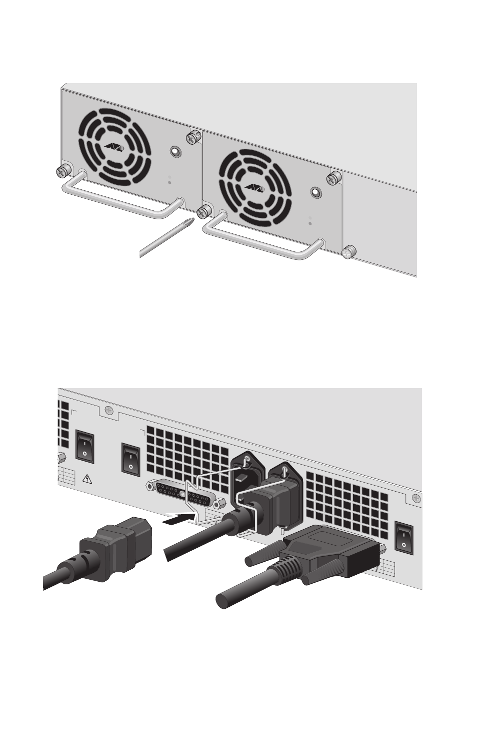
6. Using a # 1 Phillips screwdriver, tighten the two captive screws to
secure the module in the AT-RPS3104 system (see Figure 17).
Figure 17. Tightening the Captive Screws on the AT-PWR3101 Module
7. Connect an AC power cord to the appropriate AC connector on the
back panel of the AT-RPS3104 system (see Figure 18). (The AC
power cords ship with the AT-RPS3104 system, not with the
AT-PWR3101 modules.)
Figure 18. Connecting the AC Power Cord to the AT-RPS3104 System
STATUS
AT-PWR3101
POW
ER
FAULT
STATUS
AT-PWR3101
POW
ER
FAULT
VDC
A MAX
8.5
3
15
OUTPUT V
DC
A MAX
+48
+12
+3.3
8.5
3
15
OUTPUT V
DC
A MAX
+48
+12
+3.3
8.5
3
15
WARNING
This uni
t has more than o
ne po
wer inpu
t. To reduce the
risk of electric shoc
k, disconn
ect all po
wer inpu
ts
before ser
vicing un
it.
RPS OUTPUT B
B
A
AC INPUT
100-240
VAC
~
RPS OUTPUT
A
ON
OFF
B
ON
OFF
C
ON
OFF
A