Rps input – Allied Telesis AT-PWR3101 User Manual
Page 31
AT-RPS3104 and AT-PWR3101 Installation Guide
31
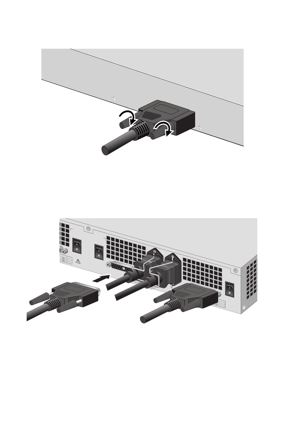
10. Tighten the thumb screws on the connector to secure the cable to the
switch (see Figure 21).
Figure 21. Securing the RPS Cable to the Switch
11. Plug the other end of the RPS cable into the appropriate RPS
OUTPUT connector on the back panel of the AT-RPS3104 system
(see Figure 22).
Figure 22. Connecting the RPS Cable to the AT-RPS3104 Unit
12. Tighten the thumb screws on the connector.
13. Turn the appropriate On/Off power switch on the back panel of the
AT-RPS3104 system to the On position. Each module slot in the
AT-RPS3104 system has a separate power switch.
RPS INPUT
OUTPUT VDC
A MAX
+48
+12
+3.3
8.5
3
15
OUTPUT V
DC
A MAX
+48
+12
+3.3
8.5
3
15
OUTPUT V
DC
A MAX
+48
+12
+3.3
8.5
3
15
WARN
ING
This uni
t has m
ore than o
ne po
wer inpu
t. To reduce the
risk of electric shoc
k, disconn
ect all po
wer inpu
ts
before ser
vicing un
it.
RPS OUTPUT B
B
A
AC INPUT
100-240V
AC
~
RPS OUTPUT
A
ON
OFF
B
ON
OFF
C
ON
OFF
A