Connectors and port pinouts, Rj-45 connector and port pin layout, Table 6. mdi pin signals (10base-t or 100base-tx) – Allied Telesis AT-GS950/24 User Manual
Page 42
Appendix A: Technical Specifications
42
Safety and Electromagnetic Emissions Certifications
EMI/RFI:
FCC Class A, EN55022 Class A,
CISPR Class A
Immunity:
EN55024
Electrical Safety:
EN60950 (TUV), UL60950 (
c
UL
us)
,
C-TICK, CE
Connectors and Port Pinouts
This section lists the connectors and connector pinouts for the
AT-GS950/16 and AT-GS950/24 switches and their components.
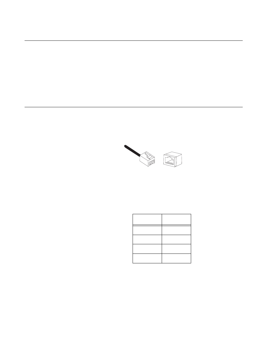
Figure 15 illustrates the pin layout for an RJ-45 connector and port.
Figure 15. RJ-45 Connector and Port Pin Layout
Table 6 lists the RJ-45 pin signals when a twisted pair port is operating in
the MDI configuration.
Table 6. MDI Pin Signals (10Base-T or 100Base-TX)
Pin
Signal
1
TX+
2
TX-
3
RX+
6
RX-
8
8
1
1
This manual is related to the following products: