Collapsed backbone, Figure 5. collapsed backbone topology – Allied Telesis AT-GS950/24 User Manual
Page 23
AT-GS950/16 and AT-GS950/24 Gigabit Ethernet Smart Switches Installation Guide
23
Collapsed
Backbone
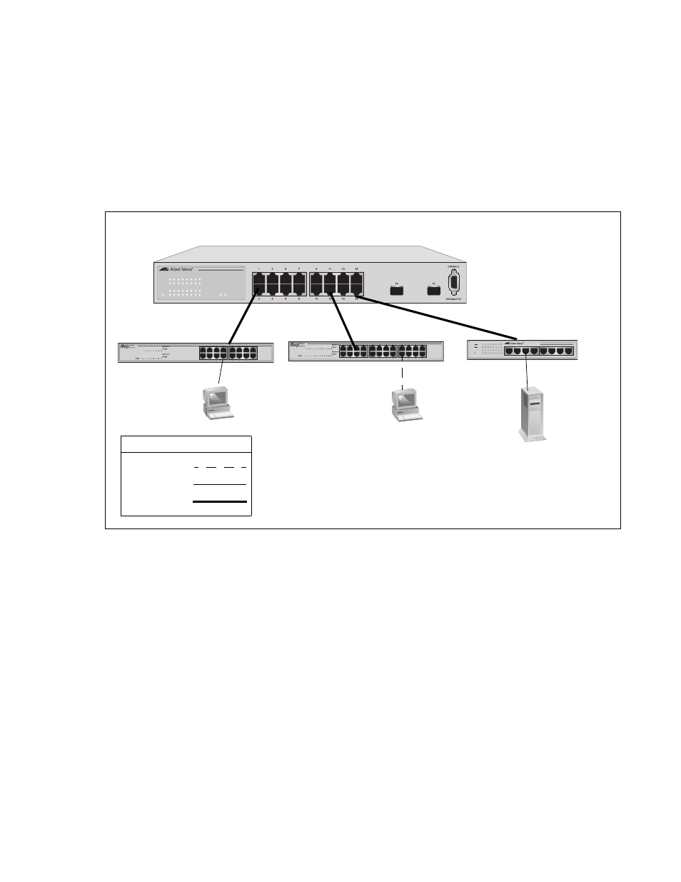
In the topology illustrated in Figure 5 the AT-GS950/16 is connected to
other managed and unmanaged Ethernet switches to form a collapsed
backbone topology. The AT-GS950/16 Switch functions as the focal point
of the network by transferring Ethernet frames between the switches. This
topology reduces the amount of unnecessary traffic in each workgroup,
because the AT-GS950/16 Switch transfers frames only when the source
and destination end nodes are located on different switches. This frees up
bandwidth and improves network performance
Figure 5. Collapsed Backbone Topology
600
601
561
M
0
0
1
T
C
A
/
K
N
I
L
X
D
F
R
E
W
O
P
2
E
8
/
0
0
9
S
G
-
T
A
h
c
t
i
w
S
t
e
n
r
e
h
t
E
t
i
b
a
g
i
G
T
-
E
S
A
B
0
0
0
1
/
0
0
1
/
0
1
M
0
1
M
0
0
0
1
1
3
4
5
8
7
6
2
1
3
4
5
6
7
8
AT-GS950/16 Switch
LINK/ACT
SPEED
LINK/ACT
SPEED
POWER
15
16
LINK/ACT
1
3
5
7
9
11
13
15
2
4
6
8
10
12
14
16
AT-GS950/16
16-Port 10/100/1000Mbps + 2 SFP Combo WebSmart Switch
1295
Legend
100 Mbps
1000 Mbps
10 Mbps
AT-GS900/16 Switch
AT-GS900/24 Switch
AT-GS900/8E Switch