Leds – Allied Telesis AT-GS950/24 User Manual
Page 19
AT-GS950/16 and AT-GS950/24 Gigabit Ethernet Smart Switches Installation Guide
19
LEDs
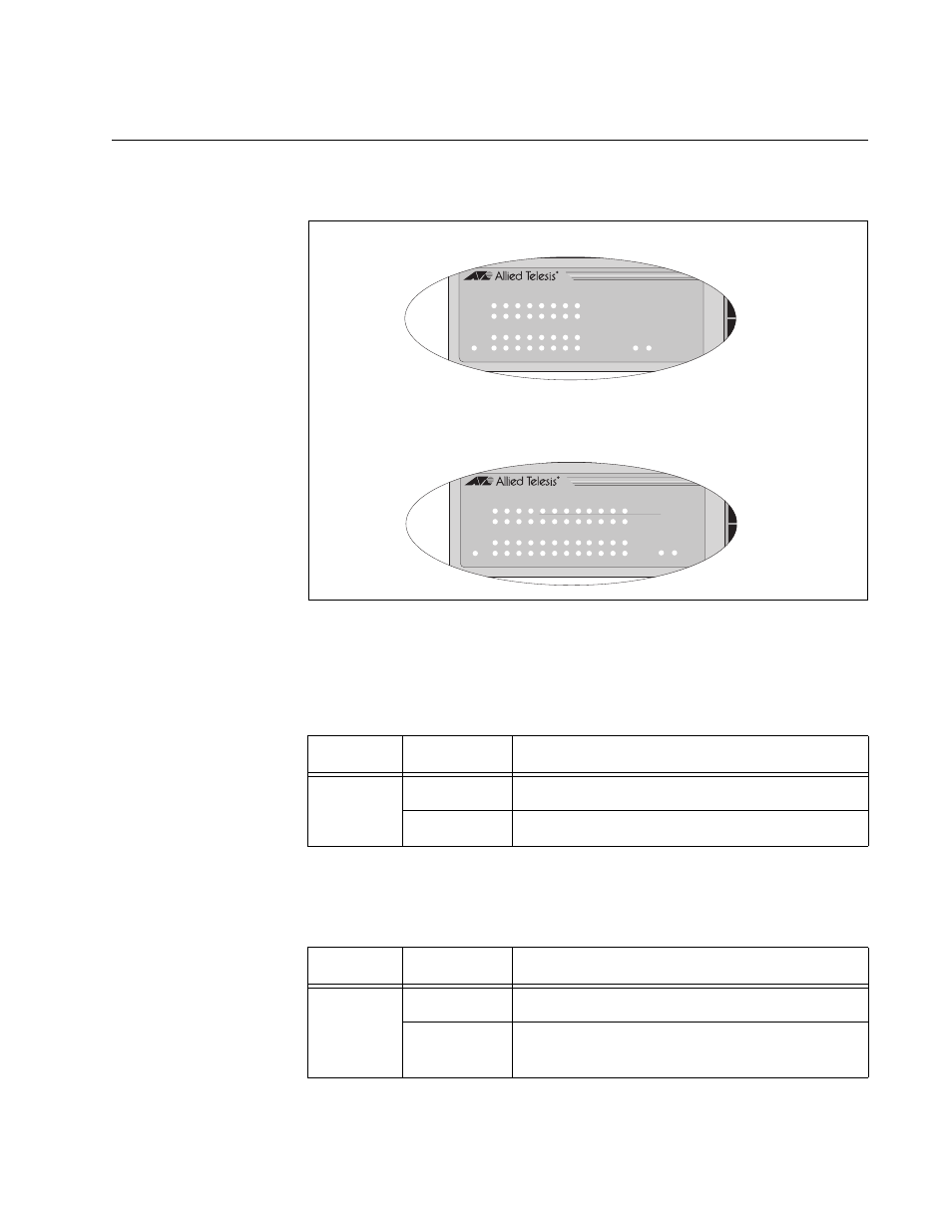
The LEDs shown in Figure 3 display system and port status information.
Figure 3. AT-GS950/16 and AT-GS950/24 System and Port LEDs
Table 2 describes the system LEDs.
Table 3 describes the LEDs for the 10/100/1000Base-T ports.
Table 2. System LEDs
LED
State
Description
POWER
Off
The switch is not receiving power.
On
The switch is receiving power.
Table 3. 10/100/1000Base-T Port LEDs
LED
State
Description
SPEED
On
The port is operating at 1000 Mbps.
Off
The port is operating at 10/100 Mbps or no
link is established.
AT-GS950/16
AT-GS950/24
1297
LINK/ A C T
SPEED
LINK/ A C T
SPEED
P O WE R
15 16
LINK/ A C T
1 3 5 7 9 11
13
15
2 4 6 8 10
12
14
16
A T -GS950/16
16- P o r t 10/100/1000Mbps + 2 SFP Combo W ebSma r t Switch
1298
P O WE R
23
24
LINK/ACT
1 3 5 7 9 11
13
15
2 4 6 8 10
12
14
16
A T -GS950/24
24-P or t 10/100/1000Mbps + 2 SFP Combo W ebSma r t Switch
LINK/ACT
SPEED
LINK/ACT
SPEED
17 19
21
23
18
20
22
24