Stratus, Troubleshooting (cont.) – Maximum Stratus User Manual
Page 6
STRATUS
TROUBLESHOOTING (CONT.)
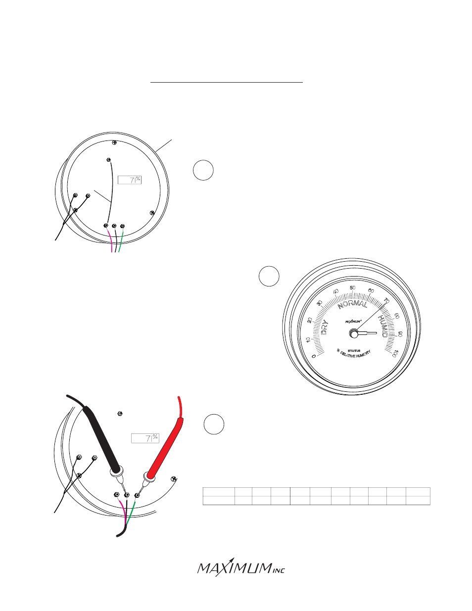
To test the sensor connect a DC voltmeter to terminals
#2 and #3. Terminal #2 is the ground terminal and #3
the positive of the meter. Use this chart to identify that
the voltage output of the sensor is correct.
If the indicator is in proper working order it will read within 2%
of the calibration test point. We recommend that you re-mount
the instrument in this mode for several hours and observe it
periodically. This will help identify intermittent problems. If the
indicator registers within 2% of the test point then the problem
is in the sensor or wire.
Use a jumper wire to connect across the test point
terminal and terminal #1. The calibration test point
has been hand-written on the back of the indicator.
5
6
7
%RH
Voltage
10
.9V
20
1.1V
30
1.4V
40
1.6V
50
1.9V
60
2.1V
70
2.4V
80
2.6V
90
2.9V
100
3.12V
1
2
3
TEST POINT 1
Test
Point:
JUMPER
WIRE
INDICATOR
1
2
3
TEST POINT 1
Test
Point:
30 Barnet Boulevard
New Bedford, MA 02745
(508) 995-2200