2 md9 emulation – Campbell Scientific MD485 RS-485 Multidrop Interface User Manual
Page 17
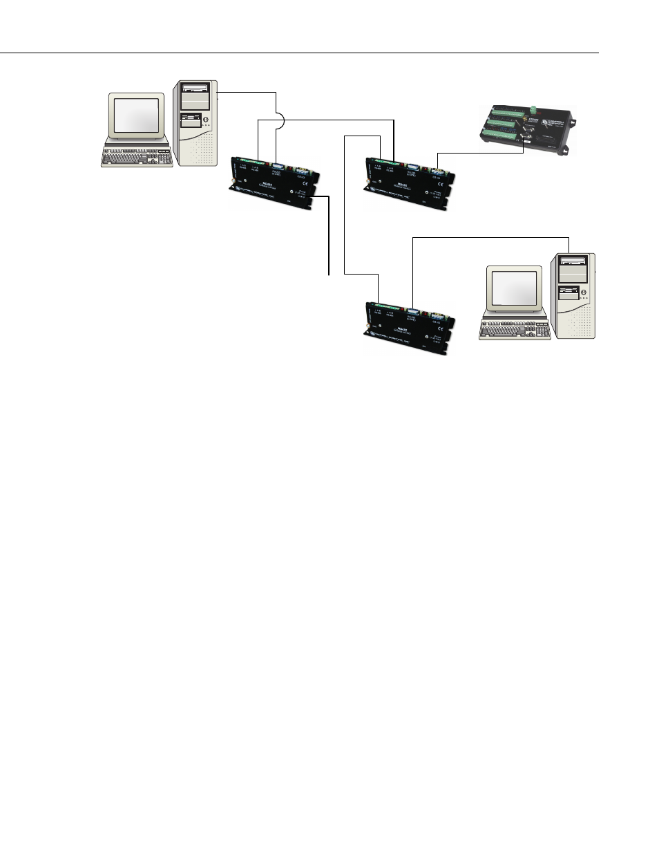
MD485 RS-485 Multidrop Interface
SCADA-PC
SCADA-PC
MODBUS
To
Wall
Transformer
FIGURE 10. Transparent Point-to-Multipoint Network
5.2 MD9 Emulation
In MD9 emulation mode, the MD485 mimics the link-oriented dialing
characteristics of the MD9. Note that the RS-485 interface is not physically
compatible with the coaxial cable used by the MD9, so an MD485 cannot be
used with an MD9. The MD9 emulation mode is not used with PakBus
dataloggers, such as the CR800, CR850, CR1000, or CR3000.
The MD485 Setup Menu is used to put the device into MD9 emulation mode.
When this option is chosen for the communication mode, an MD9 address
must also be assigned. The base MD485 should be given address 255. Remote
MD485s can be assigned addresses between 1 and 254.
In MD9 emulation mode, the MD485 looks like an MD9 to the PC, thus
allowing legacy software to use an MD485 network as if it were an MD9
network. In the LoggerNet Setup Menu, an MD9Base is inserted at the
appropriate point in the device map to represent the base MD485. Then an
MD9Remote representing each remote MD485 in the network is connected to
the MD9Base. The appropriate address for each remote MD485 must be
entered into the address field. The corresponding datalogger is then connected
to each remote in the network map.
If using PC208W, an MD9 Modem is inserted into the network map to
represent the base MD485. The remote MD485s are not shown in the network
map. Rather, the dataloggers are directly attached to the MD9 Modem. The
address of each remote MD485 is entered in the “Switch Setting of Remote
MD9” field of the corresponding datalogger.
11