Campbell Scientific CS125 Present Weather Sensor User Manual
User guide
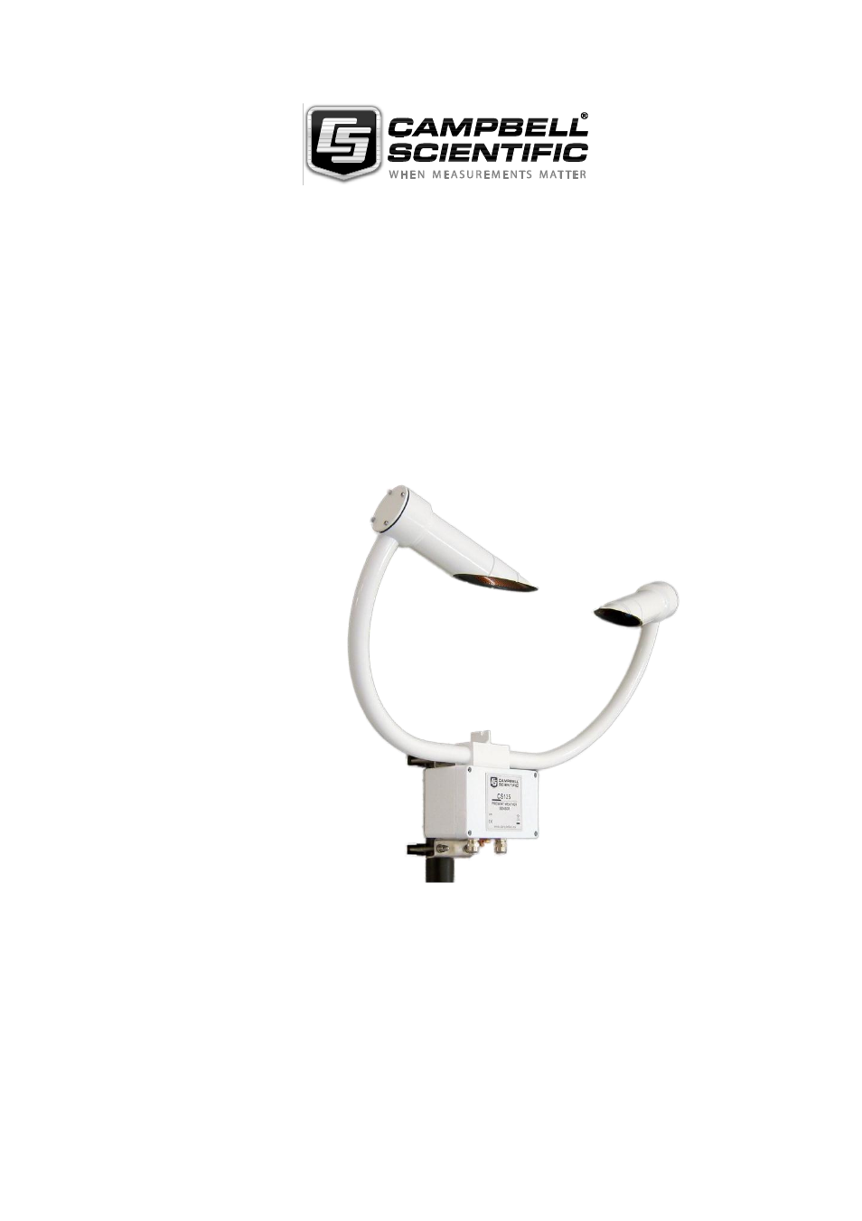
Table of contents
Document Outline
- Guarantee
- PLEASE READ FIRST
- 1. Introduction
- 1.1 Version Information
- 1.2 General Safety
- 1.3 Sensor Unit Safety
- 2. Technical specification
- 3. Electrical specification
- 4. Supported data rates for RS232 and RS485
- 5. Environmental specifications
- 6. Mechanical specifications
- 7. Installation procedure
- 7.1 Equipment grounding
- 7.2 Mounting the CS125
- 7.3 Optional Campbell Scientific Mount
- 8. CS125 internal connectors’ description
- 8.1 CS125 recommended wiring using Campbell Scientific cables
- 9. CS215 T/RH Sensor
- 10. Functions of the internal switches
- 11. Message Formats: A breakdown of the differentdefault outputs of the CS125 – Basic/Partial/Full
- 11.1 Visibility Only messages (CS120 emulation)
- 11.2 Messages with SYNOP Present Weather Codes
- 11.3 Messages with METAR Present Weather Codes
- 11.4 Example CS125 message outputs
- 11.5 SYNOP Codes produced by the CS125
- 11.6 METAR Codes produced by the CS125
- 12. Interface methods – Device ConfigurationUtility/Command line/Menu
- 12.1 Configuring a PC for talking to the CS125
- 13. Definition of the variables that can be set by theuser on the CS125
- 14. Command line mode
- 14.1 The SET command
- 14.2 The SETNC Command
- 14.3 The GET Command
- 14.4 The POLL command – Polling the CS125
- 15. Entering the CS125 menu system
- 16. Calibrating the CS125
- 17. Performing a firmware update
- 18. Cleaning
- 19. Lubricating the enclosure screws
- 20. Desiccant
- Appendix A. CS125 block diagram
- Appendix B. Example C code of the CCITTCRC
- Appendix C. Example CRBasic programs
- C.1 CRBasic read program
- C.2 CRBasic POLL program
- C.3 Example CRBasic SET program
- C.4 Example CRBasic SETNC Command
- C.5 Example CRBasic GET program
- CAMPBELL SCIENTIFIC COMPANIES