Installation, commissioning of centric grippers, Aschnitt a-a – ROHM RZP / RZP-A 3-jaw centric gripper User Manual
Page 32
Installation, Commissioning of Centric Grippers
3-jaw centric grippers
ID 1104572 Operating Manual RZP; RZP-A
Röhm GmbH, Dillingen Works Röhmstr. 6, 89407 Dillingen/Donau, GERMANY, Tel. (49)9071/508-0
Page 32 of 39
RZP
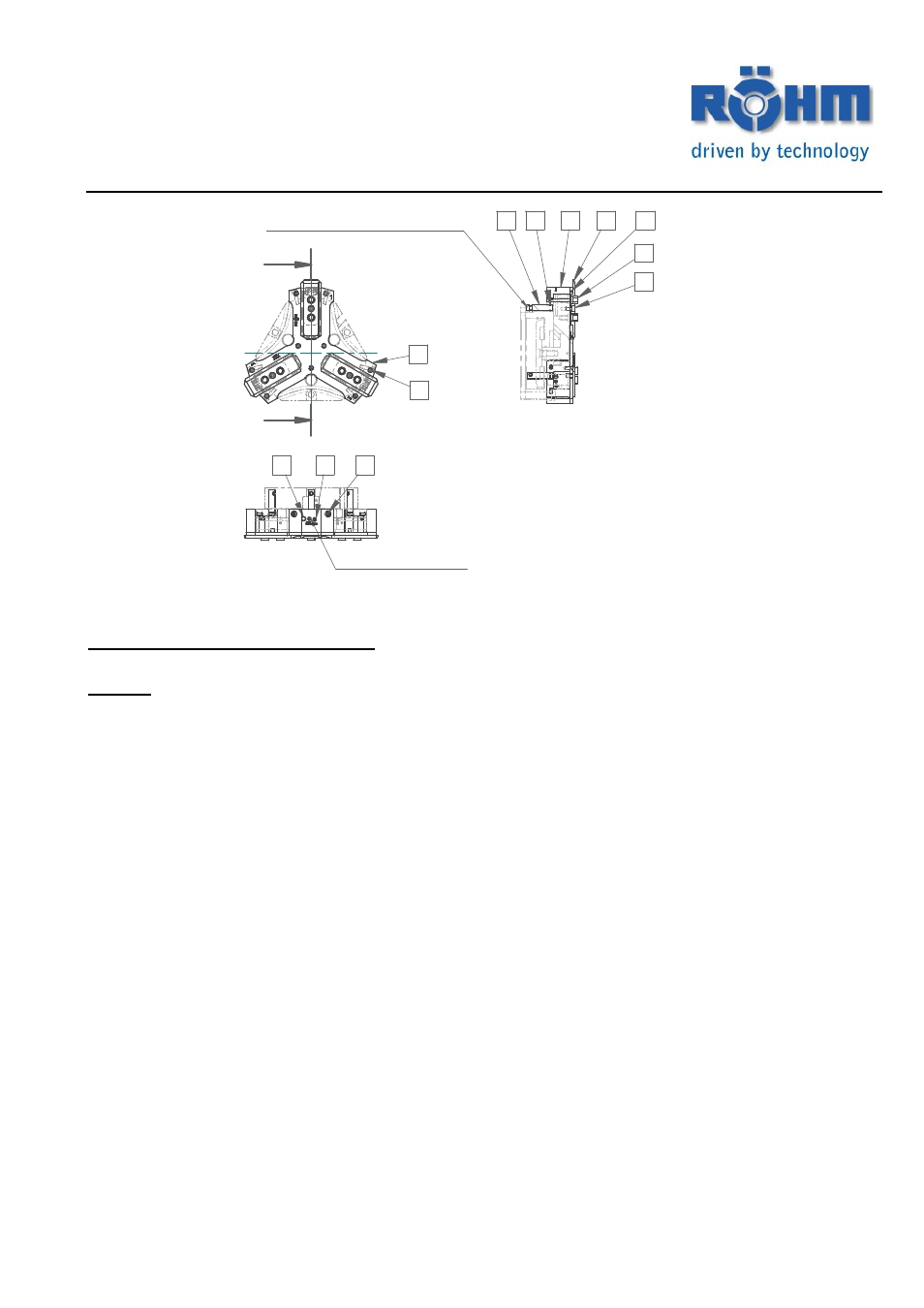
Installation of the RZP dirt cover
Caution: The energy supply must be switched off during installation of the dirt cover on the gripper.
Observe also the safety precautions. Please refer to the catalogue for the connection dimensions of the
respective gripper size.
1) Before installing the dirt cover on the RZP gripper, the lower cover must be loosened and
removed from the gripper.
2) The connection surfaces must be clean and free from dirt.
3) Install the covers (item 62) on left and right on the end faces of the gripper and tighten
the mounting bolts slightly.
4) Now place the cover plate (item 61) into the gripper and bolt this with the hexagon head
bolts to the gripper and the side covers (item 62). Tighten all the mounting bolts.
5) Take the Quad-Ring supplied and place it into the groove of the cover plate.
6) Install the intermediate jaw on the base jaw. The intermediate jaw is centered on the
base jaw by means of the centering sleeves. Pay attention to the clearances of the wiper
surfaces on the intermediate jaw – surfaces may have different lengths. The
intermediate jaw must protrude by the same amount on both sides after positioning.
When the gripper is open, the overhang corresponds to the jaw stroke of the gripper.
Fasten the intermediate jaw to the base jaw using cylinder screw (item 68). After
installing the intermediate jaws, check the free movement of the jaws.
7) Install the centering sleeves on the intermediate jaw.
A
A
Schnitt A-A
Gewindebohrung mit
Gewindestift DIN 913 verschlossen
Beim Herausschrauben des Gewindestiftes - Verstellmöglichkeit der
Verschiebeklötze 1 u. 2 durch Verdrehen der Verstellspindel
63
62
65
70
71
68
64
Bei Verwendung von induktiven Näherungsschaltern
Dichtbolzen Pos. 64 entfernen
72
61
67
69
66