ROHM RGP Long stroke gripper User Manual
Page 9
Mounting, Initial operation of the parallel gripper
Parallel Long Stroke Gripper RGP
Id.1140167 Operating Instructions RGP
Röhm-Tool GmbH, Röhmstr. 6, 89407 Dillingen/Donau, GERMANY, Tel. (49)9071/508-0
Page
9 of 14
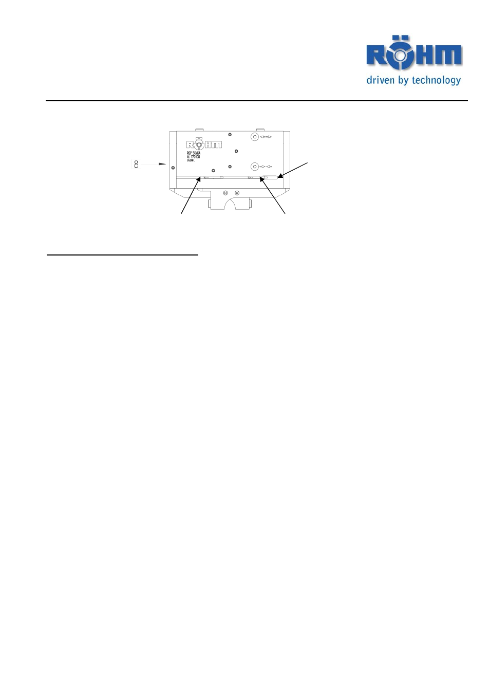
Relief cut to insert the
Solenoid switches
Solenoid switch 1
Solenoid switch 2
Fitting the magnetic field sensors
Undo the screws of the factory-mounted clamp holder before mounting the electronic solenoid
switches and slide these together with the slot nuts out of the T-shaped groove through the relief
cut.
Query: Gripper open
1) Set the gripper to the “OPEN” position“
2) Slide the magnetic field sensor 1 through the relief cut into the T-shaped groove until this hits
the cover Pos.8.
3) Secure the solenoid switch in this position by clamping it in the T-shaped groove by tighten-
ing the grub screw (max. 0.1 Nm).
4)
Test the function by closing and opening the gripper.
Query: Gripper closed
1) Set the gripper to the “CLOSED” position
2) Slide the magnetic field sensor 2 through the relief cut into the T-shaped groove, until this
reaches its first switching point.
3) Secure the solenoid switch in this position by clamping it in the T-shaped groove by tighten-
ing the grub screw (max. 0.1 Nm).
4) Test the function by closing and opening the gripper.
Query: Workpiece gripped
External gripping
1) Clamp the part you wish to grip.
Proceed as described above in points 2 - 4 under
>>Gripper closed<< .
Internal gripping
2) Clamp the part you wish to grip.
Proceed as described above in points 2 - 4 under
>>Gripper open<<.