Power through db9 jumper, Protocol select jumpers – Matrix Orbital GLK24064-16-1U User Manual
Page 15
10
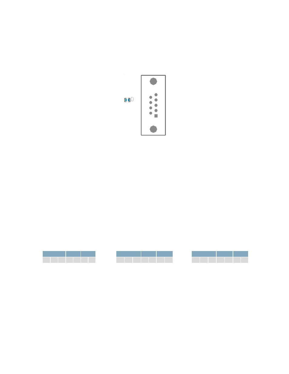
Power Through DB9 Jumper
In order to provide power through pin 9 of the DB-9 Connector you must connect the Power Through
DB-9 Jumper labelled D, as illustrated below. This connection can be made using a zero ohm resistor,
recommended size 0603, or a solder bridge. The GLK24064-16-1U allows all voltage models to use the
power through DB-9 option, see the specifications in Table 51 for voltage requirements.
Power Through DB9 Jumper
Protocol Select Jumpers
The Protocol Select Jumpers provide the means necessary to toggle the GLK24064-16-1U between RS-
232, TTL and I²C protocols. As a default, the jumpers are set to RS-232 mode with solder jumps on the
232 jumpers. In order to place the display module in I²C mode you must first remove the solder jumps
from the 232 jumpers and then place them on the I
2
C jumpers. The display will now be in I²C mode and
have a default slave address of 0x50, unless it has been changed. Similarly, in order to change the
display to TTL mode, simply remove the zero ohm resistors from the 232 or I²C jumpers and solder them
to the TTL jumpers. Protocol tables are shown below where an `X` designates a connected jump while
an ‘O’ signifies an open connection.
Table 7: RS232 Protocol Settings
RS232
TTL
I
2
C
X X X 0 0 0 0
Table 8: TTL Protocol Settings
RS232
TTL
I
2
C
O O O X X O O
Table 9: I
2
C Protocol Settings
RS232
TTL
I
2
C
O O O O O X X