Hardware, Standard model, Power/communication header – Matrix Orbital GLK24064-16-1U User Manual
Page 14: Serial db9 connector, 4 hardware, 1 standard model
9
4 Hardware
4.1 Standard Model
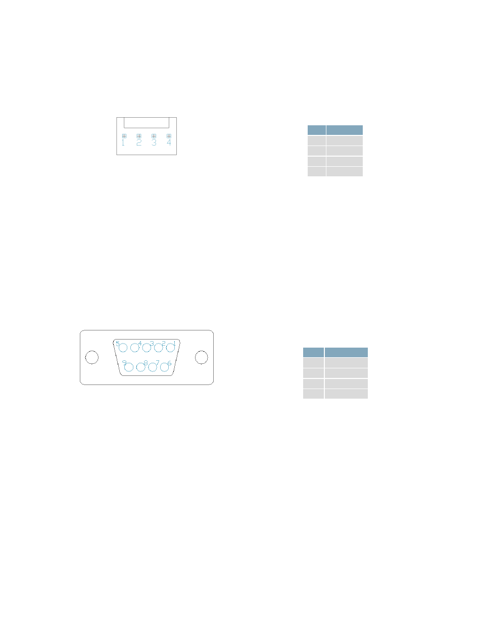
Power/Communication Header
Figure 9: Communication/Power Header
Table 5: Communication/Power Pinout
Pin Function
1
Vcc
2
Rx (SCL)
3
Tx (SDA)
4
Gnd
The Communication/Power Header provides a standard connector for interfacing to the GLK24064-16-
1U. Voltage is applied through pins one and four of the four pin Communication/Power Header. Please
ensure the correct voltage input for your display by referencing the electrical specifications in Table 51
before connecting power. Pins two and three are reserved for serial transmission, using either the RS-
232/TTL or clocking data through the I²C protocol, depending on what has been selected by the Protocol
Select Jumpers. The versatile Tyco 640456-4-LF style header employed here can be mated to a wide
array of female connectors for a perfect fit in any project.
Serial DB9 Connector
Figure 10: Serial DB9 Connector
Table 6: Serial DB9 Pinout
Pin
Function
5
Gnd
3
Rx
2
Tx
9
NC/Vcc*
The GLK24064-16-1U provides a DB-9 Connector to readily interface with serial devices using EIA232
standard signal levels. It is also possible to communicate at TTL levels of 0 to +5V by setting the Protocol
Select Jumpers to TTL. As an added feature it is also possible to apply power through pin 9 of the DB-9
Connector in order to reduce cable clutter. A standard male DB9 header will provide the perfect mate
for this connector.
*Note:
Do not apply voltage through pin 9 of the DB-9 Connector AND through the Communication/Power Header
at the same time.