3 connections, 1 connector pinout – Matrix Orbital GLK12232-25-SM Legacy User Manual
Page 9
NOTE This procedure does not change settings in the memory chip, it uses default set-
tings stored in the main processor. This allows the user to communicate with the display
when all other communications are lost. Once able to communicate with the display, the
user may then change the default settings in the memory chip.
2 Memory Chip Lock Down
The display uses a memory chip to store speed, start up screen contrast, I
2
C setting and other settings.
When everything has been changed to the desired settings and the unit is in a finished product or in the field,
locking down the memory chip so no settings can be changed might be desirable. This is only to be done
by knowledgeable people. Any damage to the display by this procedure resulting from user error will not be
covered under the Manufacturer’s Warranty.
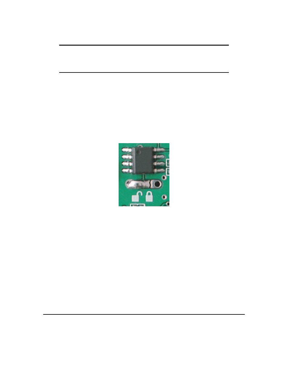
Figure 2: UnLocked Position
To lock down the memory chip, unsolder the jumper as shown in the UNLOCKED picture above and
solder the jumper in the LOCKED position. This will lock down the memory chip, not allowing anything to
be changed inside it until the jumpers are restored to their original position.
3 Connections
3.1 Connector Pinout
Refer to the diagram below for this chapter.
Matrix Orbital
GLK12232-25-SM
5