Matrix Orbital GLK12232-25-SM Legacy User Manual
Page 12
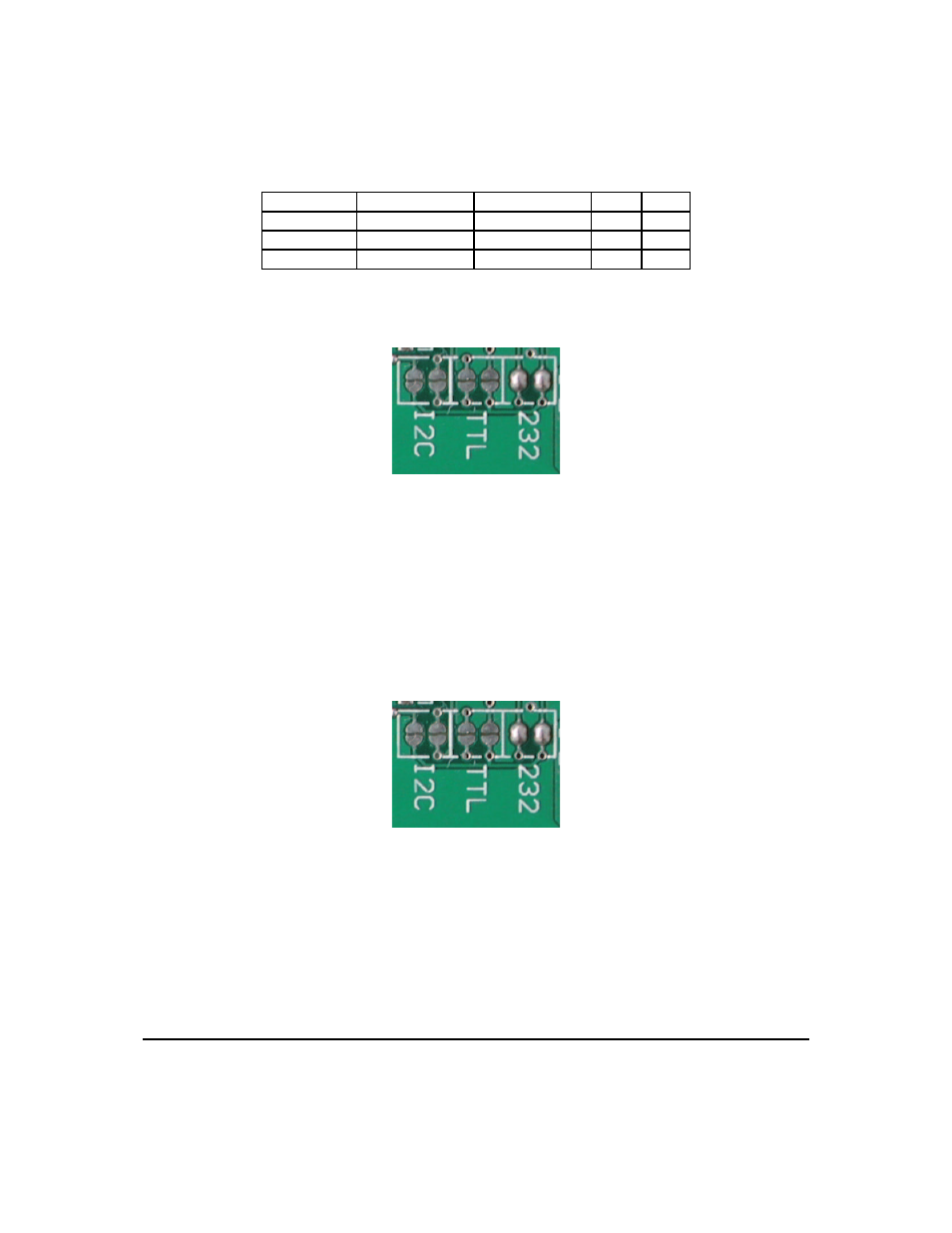
Table 1: RS-232 Pinout
Pin Number
Direction
Description
LCD
Host
2
Data from LCD
Data out (LCD)
Tx
Rx
3
Data to LCD
Data in (LCD)
Rx
Tx
5
-
Ground
gnd
gnd
Please see the following figure below for the default RS232 configuration.
Figure 5: Default RS232 Configuration
3.1.3 TTL Communications
This device complies with the EIA232 standard in that it uses signal levels from +/-12V to +/- 12V. It will
also operate correctly at TTL (0 to +5V) levels. To configure to TTL mode you must remove the jumpers
from the RS232 location and place new jumpers on the indicated TTL setting. Please see the figure below
for TTL configuration.
Figure 6: TTL Connections
3.1.4 I
2
C Communications
The display has I
2
C communications running at 100 Kbps and up to 127 units on a single communica-
tions line. The I
2
C data line operates on 5 volt CMOS levels. The display does not work on I
2
C by default.
To configure to I
2
C mode you must remove the jumpers from the RS232 location and place new jumpers on
Matrix Orbital
GLK12232-25-SM
8