Gnd co l 1 r o w 1 gnd – Matrix Orbital GLK12232-25-SM Legacy User Manual
Page 21
6.1 General
The display keypad interface processes the keypad row / column matrix into a serial (RS-232 or I
2
C)
data byte stream. Aside from this processing, the keypad has no effect on the display. If it is necessary to
send keystrokes to the display, they must be routed through the micro-controller.
6.2 Connections
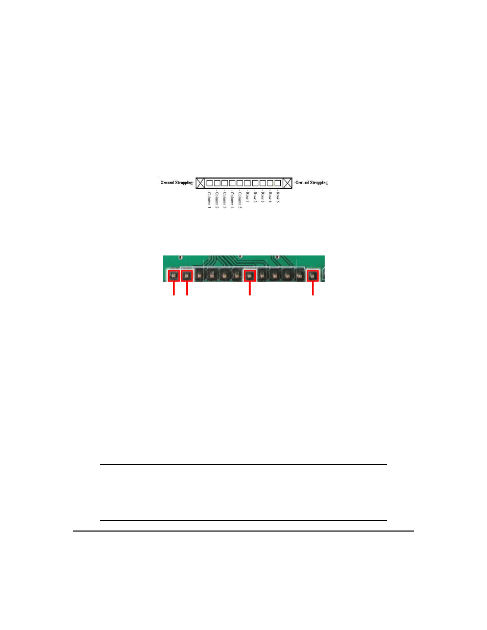
Figure 12: Keypad Connector
GND CO
L
1
R
O
W
1
GND
Figure 13: Keypad Connector
The connector is not ’keyed’ so the keypad will probably plug in either of two ways. The display will
not be damaged by reversing the connector. However, the keypad will generate a different ASCII character
mapping for each position. If the connector has fewer than 10 pins it should be centered on the display
connector.
The diagram shows the logical layout (row 1, column 1 in upper left). The connector for the keypad is a
10 pin 0.1" spacing male header. Pins 1 through 5 are columns and pins 6 through 10 are rows. The keypad
is scanned whenever a key is pressed; there is no continuous key scan. This means that key presses are dealt
with immediately without any appreciable latency. This also prevents electrical noise which is often caused
by continuous key scans.
NOTE Please note that keypads may be laid out in a different pattern. If this is the
case, the user will need to interpret the key codes differently. Also included are two extra
pins on each end of the connector to be used for ground strapping. This can be used
in conjuntion with your keypad if a ground strap connection is required or if a common
ground connection is needed.
Matrix Orbital
GLK12232-25-SM
17