Gnd tx rx +5v +5v gnd gnd +12v – Matrix Orbital GLK12232-25-SM Legacy User Manual
Page 11
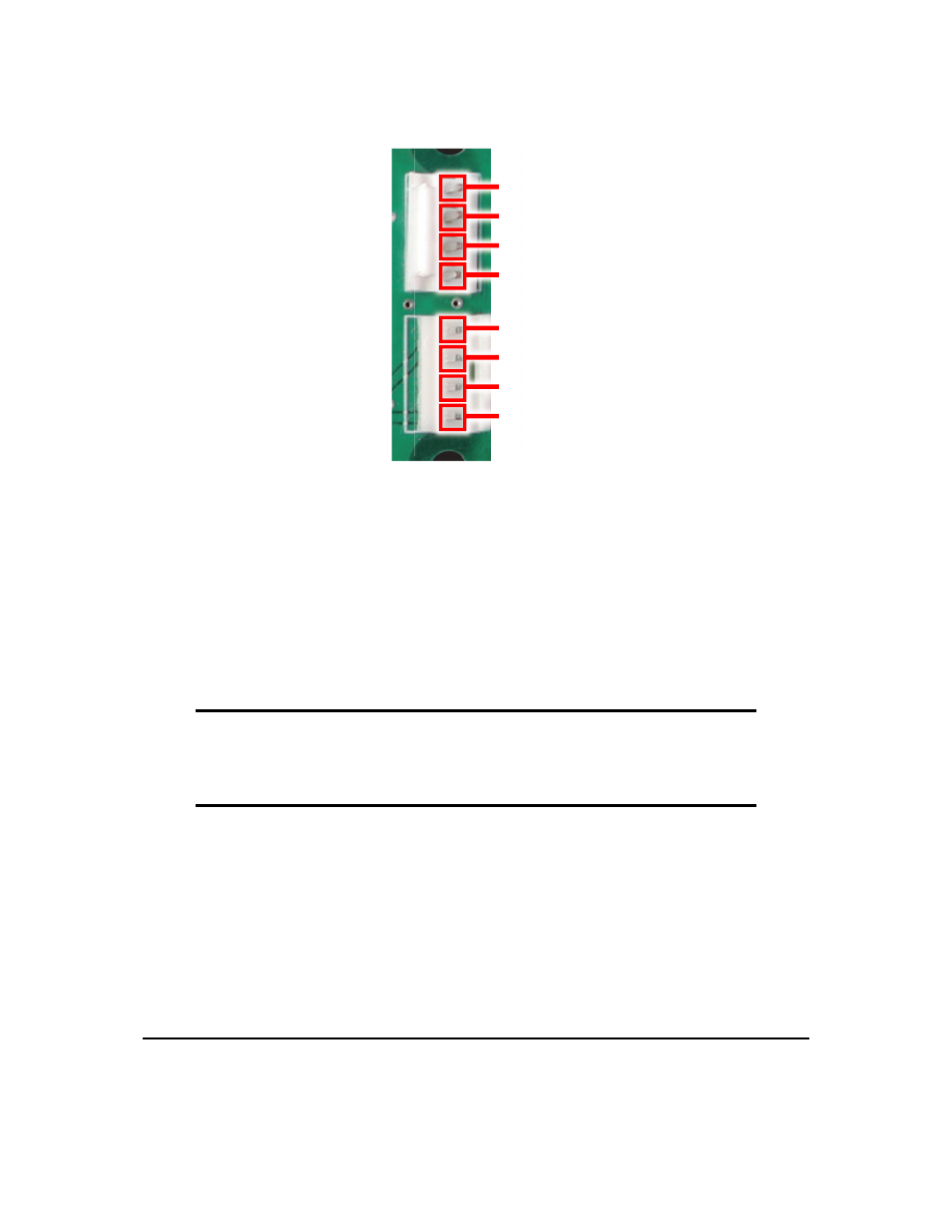
GND
TX
RX
+5V
+5V
GND
GND
+12V
Figure 4: Power and Data Configuration
If a standard module is ordered a 5 Volt input must be applied. You have two options for this to be
applied. You can apply power and communication via one cable through the top connector or apply power
via an unmodified floppy power cable through the bottom connector and power/ground through the top
connector.
If a wide voltage module is ordered a 7-15 Volt input must be applied. There is two options for this to
be applied. Power and communication can be applied via one cable through the top connector, or power can
be applied via an unmodified floppy power cable through the bottom connector with data and ground being
connected to the top connector.
NOTES
• A common ground should be used at all times.
• Each module ordered has specific voltages and cannot be interchanged.
3.1.2 RS-232 Communications
A 4 pin SIP connector can be connected to a Matrix Orbital supplied PC cable .
The RS-232 connector on the PC cable is wired so that a standard ’straight through’ 9 pin D-sub cable
may be used to connect the modules to a standard serial port such as COM ports on PCs. To connect this
module to a PC, a 1 foot serial cable and a 4-BR cable are needed. These accesories can be purchased at
the following link: www.matrixorbital.com/pages/accessories.asp?CatID=5. This device complies with the
EIA232 standard in that it uses signal levels from +/-12V to +/- 12V. It will also operate correctly at TTL (0
to +5V) levels. To use standard RS-232 no modifications are required.
Matrix Orbital
GLK12232-25-SM
7