Wiring diagram, Gauge, A) (b) (–) – Ashcroft 2236 - Digital Sanitary Pressure Gauge User Manual
Page 18
– 18 –
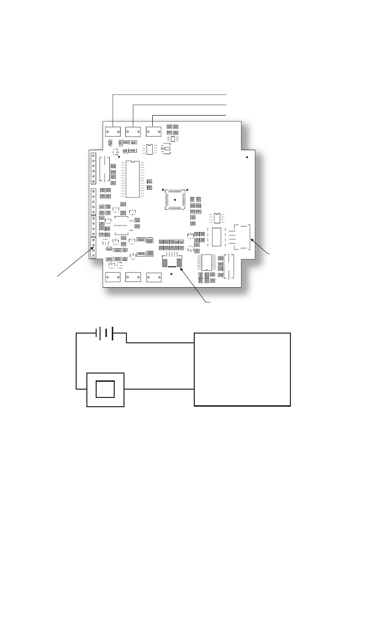
WIRING DIAGRAM
LOOP+
LOOP–
T7
D9
D7
Y1
D10 C14 T9
U5
V1
F1D1
C3
C7
R7
R2
J1
1
1
J6
C2
R22 R20
C17
D11
U7
D14
D1
C15
R18
D5
R23
R24
D13
R14
R16
J3
J7
1
Q4
D16
D6
D15
D3
D12
T10
T12
T11
+24V
GND
EGND
FID3
321CO21–
D8
Q2
J5
J3
C4
R9
R10
R11
R12
R13
Q1
C10
C9
R6
C5
L1
U4
FO7
R8
FID4
V2
R1
R5
C1
R4
C6
C8
DQ/TB 2003
Y2
J2
FID2
V6
R21
Q3
T8
ECND
FID6
FID5
R19
Red (+ exec.) A
Black (– exec.) B
Battery Input
Keypad Input
Sensor Input
Shield
Loop Powered 4-20mA (Type 2132)
2 conductor, 20 AWG shielded
Installation Procedure for 2132:
ƽ
ESD precautions should be taken. See page 31 for details.
1. Ensure all power is off/disconnected from the circuit.
2. Connect the red wire (A) to the positive power terminal.
3. Connect the black wire (B) to the positive terminal on the
meter.
4. Connect the negative side of the meter to the negative
power terminal.
Note: Meter should be installed on the black wire only.
+
+
–
POWER
SUPPL Y
(+)
(–)
METER
PLC
SCADA
GAUGE
–
V+
V–
Red
Black
(A)
(B) (–)