Electrical connections, Connectors, Host connector - rs-232 – MagTek IntelliStripe65 99875339 User Manual
Page 20: Host connector - usb, Power-fail capacitor connector
IntelliStripe 65, USB/RS-232 Insertion Reader
12
ELECTRICAL CONNECTIONS
Connectors
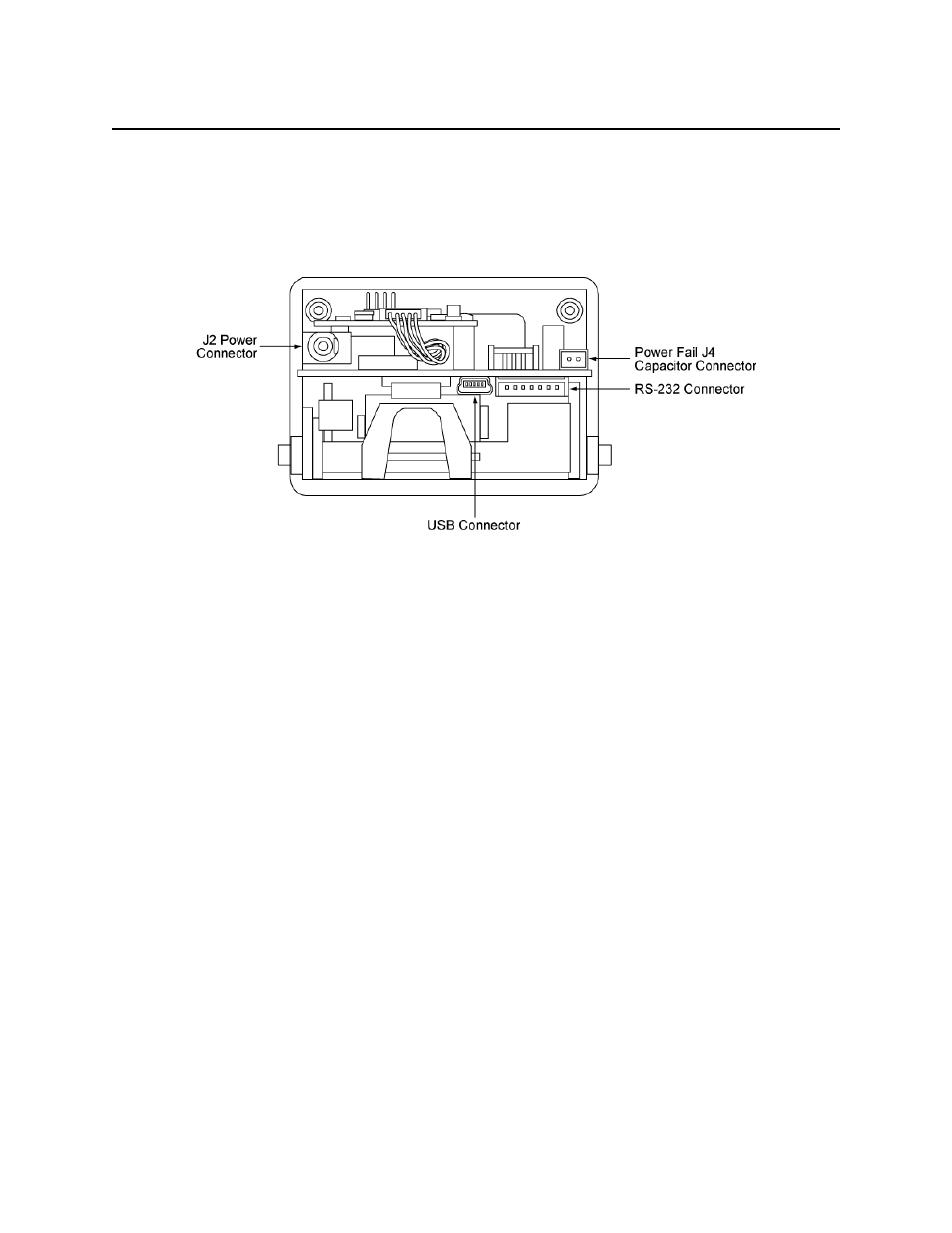
Figure 2-3 shows the positions of the rear connectors for power and communication.
Figure 2-3. Power and Communication Connections
Host Connector - RS-232
The RS-232 connector, J1, connects to the host’s power and RS-232 signals. Figure 2-3 shows
the location of the 7-pin RS-232 Connector. Table 2-1 lists the pin numbers of the connector. If
the RS-232 connection is used, the power can be supplied through the jack on the RS-232 cable
(see Figure 2-10) or via the J2 Power Connector.
Host Connector - USB
The USB connector, J11, connects to the host’s USB port. When using the USB connection,
power must be supplied via the J2 Power Connector on the back of the IntelliStripe 65. If the
USB connection is used, the power must be supplied to the J2 Power Connector.
Power-Fail Capacitor Connector
The Power-Fail Capacitor connector, J4, connects to an optional external capacitor that is used to
unlatch the card during a power failure. Pin 1 connects to the positive side of the capacitor and
pin 2 connects to the negative side (see Appendix A. Options, Power-Fail Latch Release
Option).