5 connecto rs and connections, 1 connectors on the back of the matrix, 2 db25 pin c onfiguration – Videotec SM164B User Manual
Page 50
Page 10
MNVCSM84A_0408
3.5 Connecto rs and connections
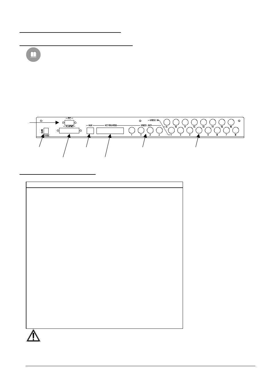
3.5.1 Connectors on the back of the matrix
The back of the SM84A / SM164A matrix has:
x 1 x 25 pin connector for connecting alarm contacts, relay contacts, VCR trigger and external alarm reset
x 4 x RJ-11 connectors for connecting the keyboards
x 1 x RJ-11 connector for connecting the telemetry receivers or multiplexers
x 1 jack connector for the power supply
x 1 x 9 pin connector for PC connection
x 4 BNC output video connectors,
x 8/16 BNC input video connectors
SM164A matrix rear view:
3.5.2 DB25 pin c onfiguration
Pin
Connection
Use
1
Alarm input 1
Alarms
2
Alarm input 2
Alarms
3
Alarm input 3
Alarms
4
Alarm input 4
Alarms
5
Alarm input 5
Alarms
6
Alarm input 6
Alarms
7
Alarm input 7
Alarms
8
Alarm input 8
Alarms
9
Alarm input 9
Alarms
10
Alarm input 10
Alarms
11
Alarm input 11
Alarms
12
Alarm input 12
Alarms
13
Alarm input 13
Alarms
14
Alarm input 14
Alarms
15
Alarm input 15
Alarms
16
Alarm input 16
Alarms
17
Alarm reset
Alarm reset
18
GND
Alarm reset
19
Trigger VCR
VCR
20
GND
VCR
21
Normally Opened Relays
Peripherals
22
Common Relays
Peripherals
23
Common alarms
Alarms
24
Common alarms
Alarms
25
Common alarms
Alarms
Alarms from 9 to 16 are only available on the SM164A model matrix.
PC
Power supply
Alarms
Aux
Line
Keyboards
Video outputs
Video Inputs