9 maintenance, 10 troubleshooting – Videotec DTMRX2 User Manual
Page 44
Page 18
MNVCDTMRX2_0351
9 Maintenance
The DTMRX2 (DTMRX224) receiver does not require any particular maintenance.
When using it we recommend it rests on a solid base, with the power supply and connecting cables positioned
so as not to get in the way of the operator.
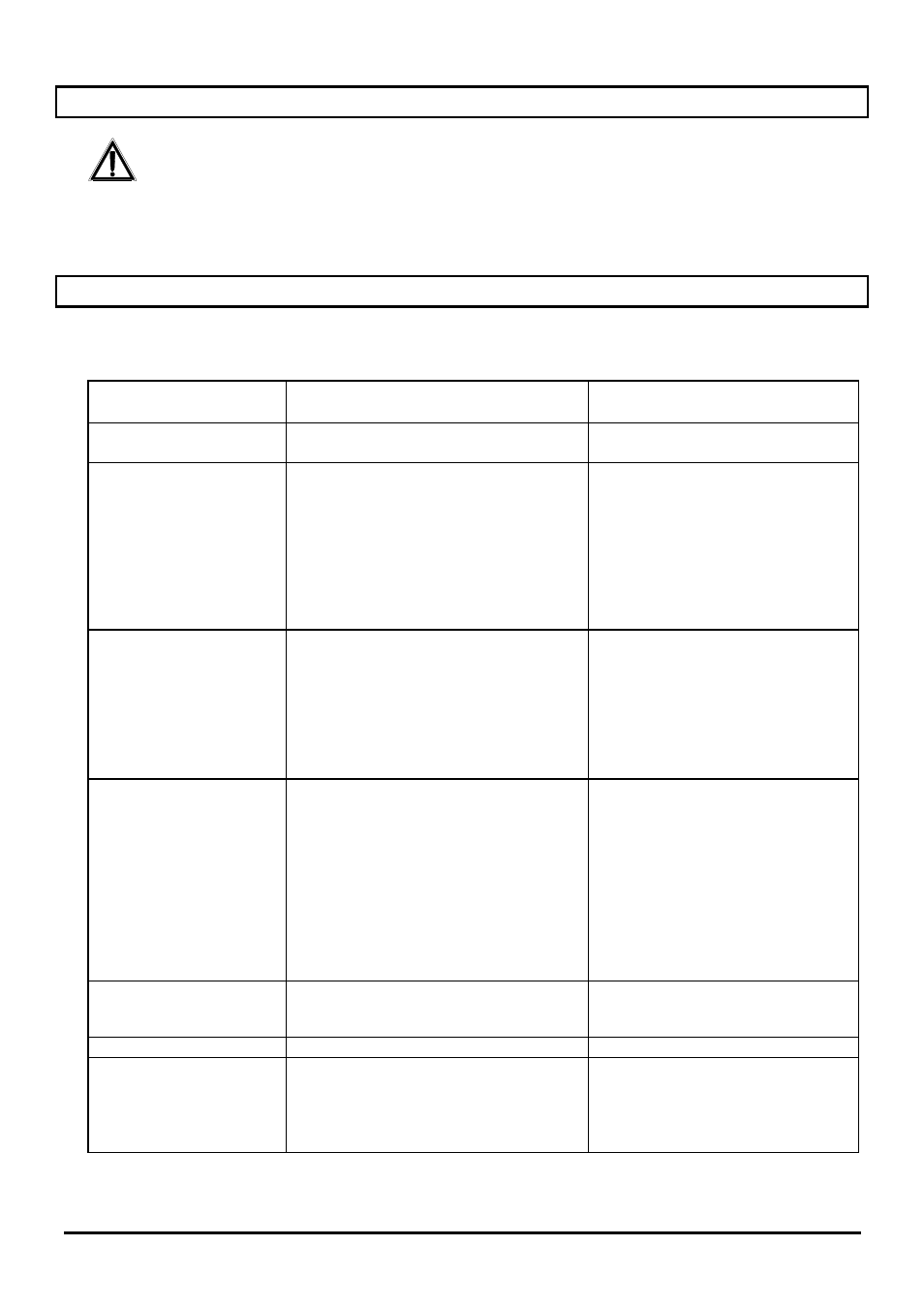
10 Troubleshooting
A great feature of the DTMRX2 (DTMRX224) receiver is that it is very easy to use, nevertheless some problems
could arise at the installation or configuration stage, or in use.
PROBLEM
PROBABLE CAUSE
REMEDY
Power supply LED off
• No
power
• Fuse
blown
• Check the power supply cable
• Replace fuse F1
Controls in RS485 are not
carried out and the power
supply LED is on
• Incorrect configuration for reception
• Incorrect baud rate or protocol
• Incorrect receiver address
• Incorrect
wiring
• Check the settings of Jumpers
JP2 and JP4.
• Check the settings of DIP Switch
SW1
• Check the address setting in the
receiver (DIP SW2)
• Check the wiring to terminals
RX485A and RX485B of J5
Controls in RS232 are not
carried out and the power
supply LED is on
• Incorrect configuration for reception
• Incorrect baud rate or protocol
• Incorrect receiver address
• Incorrect
wiring
• Check the setting of Jumper JP1
• Check the settings of DIP Switch
SW1
• Check the address setting in the
receiver (DIP SW2)
• Check the wiring to terminals
RX232 and GND
Controls in COAX mode
are not carried out and the
power supply LED is on o
• Incorrect configuration for protocol
• Incorrect configuration for receiver
address
• Incorrect
wiring
• Check DIP switch SW1
• Check the settings of DIP Switch
SW2 and make sure the address
setting corresponds to the input
video channel of the SMXXA
matrix
• Check the coaxial cable
(maximum length 350 m). Do not
use video amplification devices
between matrix, receiver and
camera.
Pan & tilt does not work
• Incorrect pan & tilt power supply
• Make sure the power supply
voltage for pan & tilt corresponds
to that supplied by the receiver
The lens does not work
• Incorrect lens voltage
• Check adjustment of trimmer TR1
In a cascade connection,
subsequent units do not
receive the controls
• Incorrect
connection
• Incorrect configuration for reception
• Incorrect baud rate or protocol
• Incorrect
address
• Check the connecting cables
• Check the Jumper settings
• Check the setting for SW1
• Check the address settings in the
units that are not working