Connectors and connections, Installation example – Videotec PTH355P User Manual
Page 22
Pag. 6
MNPTH3553803
Connectors and connections
The installation must be carried out only by qualified technical staff: an improper connection of the peripheral
units may cause the keyboard to be isolated from the rest of the system.
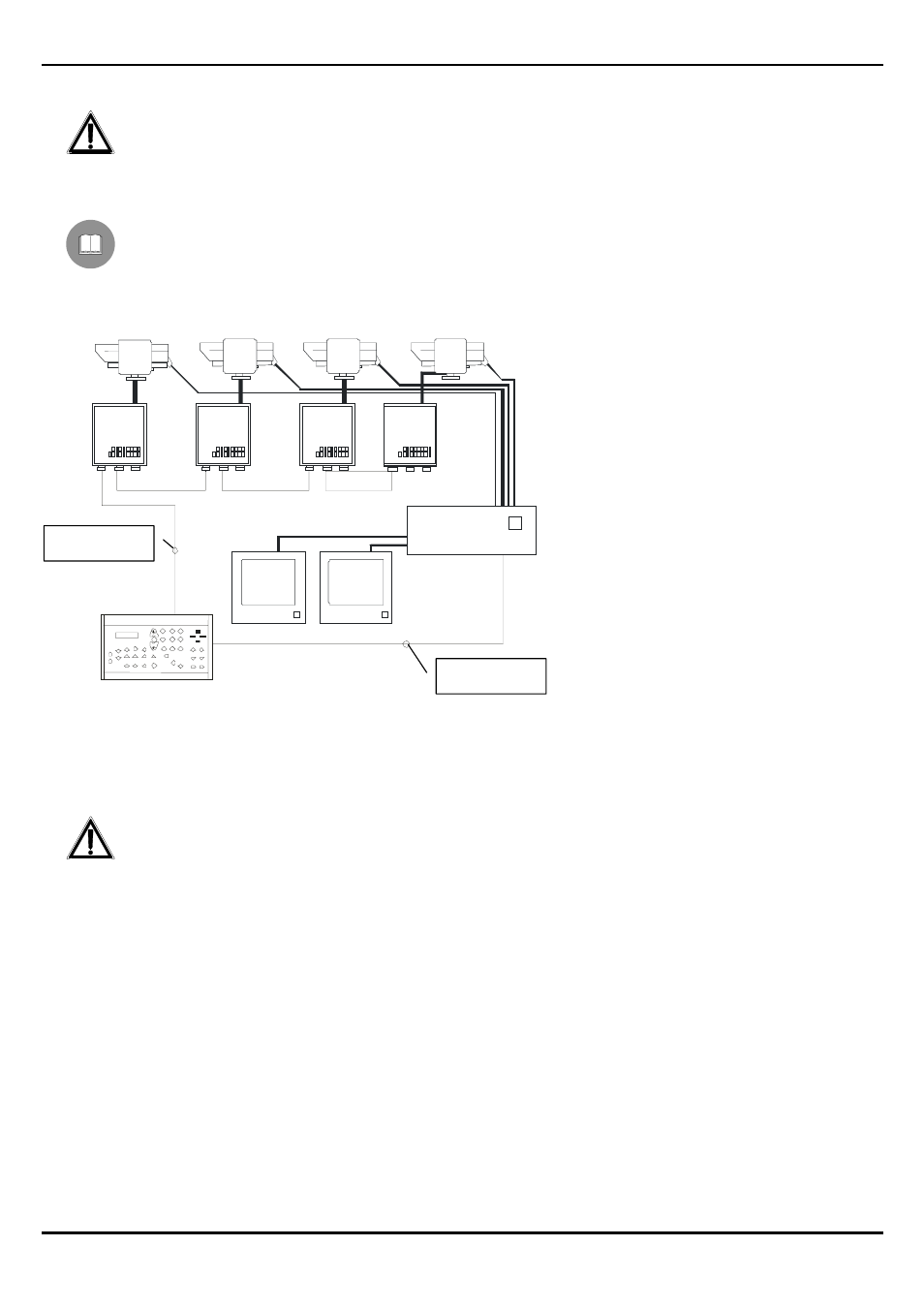
Installation example
One operator with more monitors, who controls a series of pan & tilt motors in mixed configuration (star and
cascade connection)
MATERIAL USED
Control keyboard:
x 1 DCS3 control keyboard
Video handling:
x 1 SW328 video switcher
x 2
monitors
x 4
telecameras
x Telemetry handling:
x 4 DTRXDC receivers
x 4 PTH355P pan & tilt motors
Connection Pan & Tilt – motors: 4 x 0,56 mm
2
(AWG 20)
Connection potentiometers – preset: 4 x 0,34 mm
2
(AWG 22)
The use of two different cables will be necessary for the control of the motors and for the connection with the
preset potentiometers.
DTRXDC
DTRXDC
DTRXDC
DTRXDC
SW328
DCS3
PTH355P
PTH355P
PTH355P
PTH355P
Cable with 2 wires
Cable with 2 wires