3 wiring, 1 wiper system, 3 tamper-switch signalling device – Videotec HGV User Manual
Page 10
EN - English - I
nstruc
tions manual
8
g
In the 230Vac model, a strap must be
applied between the 3 conductors to
avoid the risk of accidental contacts
between the phase wire and the
accessible conductive part.
Fig. 20
Fig. 21
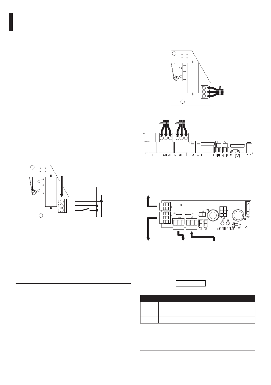
6.3.2 Connection of the power supply
terminals in input and output
J9 - Tamper
OUT
J6 - Camera OUT 24Vac/12Vdc
J7 - IN
230Vac/24Vac
J10 - OUT
230Vac/24Vac
Fig. 22
6.3.3 Tamper-switch signalling device
In order to connect the tamper-switch, refer
to terminal J9 of Fig. 22, page 8, taking the
following indications into account:
TAMPER-SWITCH CONNECTION
COM
Common switch
NC
Normally closed terminal
NO
Normally open terminal
Tab. 01
h
Operating voltage of switch,
less than 30Vac or 60Vdc.
6.3 Wiring
6.3.1 Wiper system
This section describes how to connect the
housings equipped with glass wiper system
For these versions it is not necessary to mount
any component inside the casing since the units
are supplied complete with all the elements
necessary, according to the model requested.
• Connect terminal S of clamp J1,
to the mains power phase
• Connect terminal C of clamp J1, to
the mains power neutral.
• Connect terminal P of clamp J1, to a push-
button which in turn is connected to the
mains power phase, and allows the activation
of the wiper system by keeping it pressed.
By releasing the push-button the wiper
blade will return to the rest position.
Should a receiver with wiper command be
available, connect terminals SW, PER and COM
respectively to terminals S, P and C of clamp J1.
P
S
C
J1 Terminal
Phase
Neutral
Fig. 19
g
In the 230Vac model it is necessary to
insert on the supply line, upstream of
the equipment, a unipolar 1 0 main
switch (distance of contacts opening
d>3 mm). This switch must be used as
circuit breaker to the power supply
before carrying out any maintenance
operation or opening of the equipment.