3 ethernet cable installation, 4 connection of the poe power supply board, 7 configuration – Videotec PUNTO HI-PoE User Manual
Page 9: 1 absorbed power configuration
Instruc
tions manual - English - EN
7
MNVCHEEPOE_1407_EN
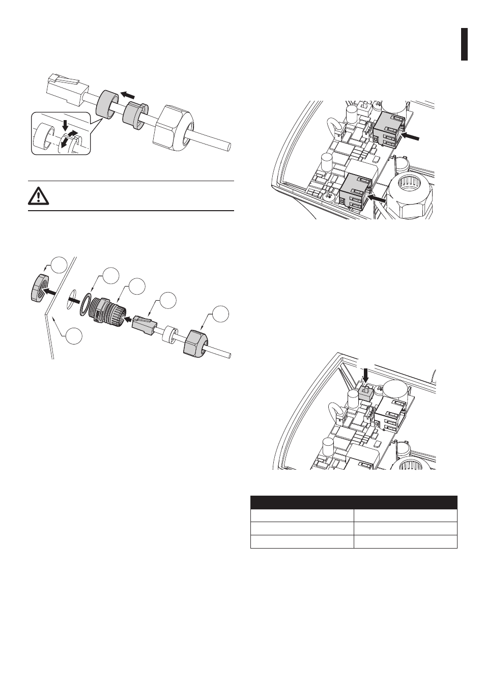
6.2.3 Ethernet cable installation
Insert the Ethernet cable in the gasket and block it as
shown in figure.
Fig. 9
Pay attention to the fixing. Tightening
torque: 7Nm max.
Pass the cable with connector RJ45 (05) through the
M20 cable gland (02). Tighten the cable gland plug
(06).
02
01
05
06
04
03
Fig. 10
6.2.4 Connection of the PoE power
supply board
Connect the PoE cable from the Power Injector to the
J1 connector.
Connect the camera to the J2 connector.
J2
J1
Fig. 11
7 Configuration
7.1 Absorbed power
configuration
Before powering the device, you must set the
maximum power consumption of the housing
operating on dip switch SW1.
SW1
Fig. 12
ABSORBED POWER CONFIGURATION
SW1
Maximum power
POE
PoE, class 3 (13W max)
POE+
Hi-PoE, class 4 (25W max)
Tab. 1