3 open the box, 4 connection of the board, 1 installing the fuse – Videotec WAS User Manual
Page 6: 2 connection of the power supply line
EN - English - I
nstruc
tions manual
4
6.1.3 Open the box
Operation valid for pump with 5m (16ft) or
11m (36ft) delivery.
Open the cover of the water-proof box and connect
as described below.
Fig. 4
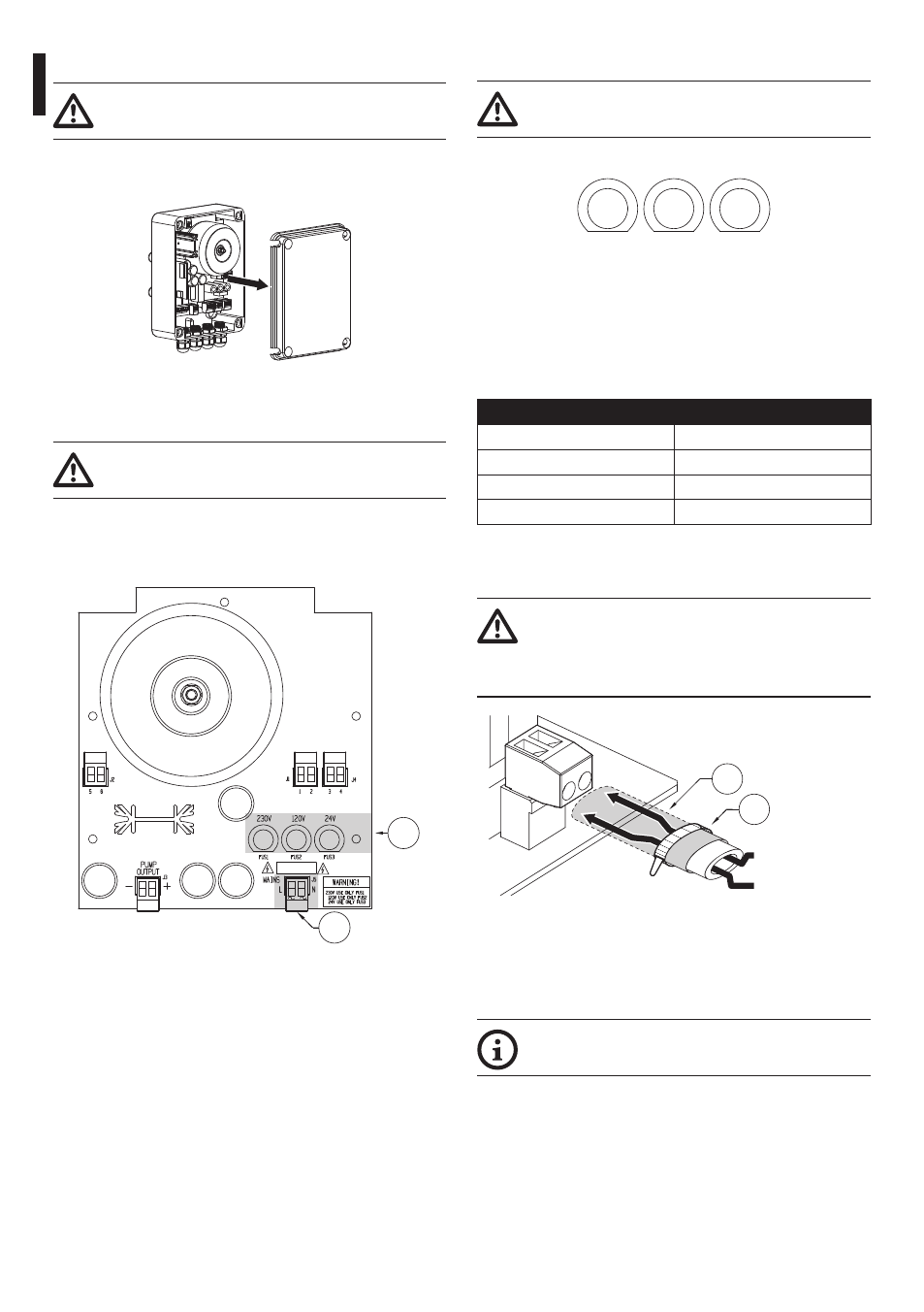
6.1.4 Connection of the board
Operation valid for pump with 5m (16ft) or
11m (36ft) delivery.
Find the position of the following on the pump
control board: fuses (01), power supply terminal
J5 (02) and pump connector J3 (03).
01
02
Fig. 5
6.1.4.1 Installing the fuse
Move the fuse into the correct fuse holder
according to the input voltage.
230V
FUS1
120V
FUS2
24V
FUS3
Fig. 6
The pump is supplied with the fuse in position FUS1
(for a 230Vac power supply).
If the power supply is different position the fuse
correctly referring to the following table.
INSTAllING THE FUSE
Voltage
Fuse holder
230Vac
Fuse in FUS1
120Vac
Fuse in FUS2
24Vac
Fuse in FUS3
Tab. 1
6.1.4.2 Connection of the power supply line
The power supply cable should also be
covered by the silicone sheath (01) supplied
for this purpose, and fastened with the
corresponding tie (02).
01
02
Neutral (N)
Phase (L)
Fig. 7
Connect the power supply terminal J5 (02) to the
electric network using a suitably sectioned cable
(minimum 1.5mm²) (Fig. 5, page 4).
Use an external switch (minimum capacity
4A, 250V) to activate the pump.