Cables, Pan & tilt connection to control units – Videotec NXPTH User Manual
Page 20
Pag. 6
MNNXPTH4403
Cables
Different types of stroke have been used in the previous examples, in order to indicate cables with different
functions:
video cable:
RG 59 coaxial cable or equivalent cable
multipolar cable:
Fix the final numbers of wires according to the following directions:
6 wires for the motion of the positioning device: right, left, up, down, autopan, common, ground
6 wires for the control of polarity reversal lenses (zoom, focus, iris)
4 wires for the control of common wire lenses (zoom, focus, iris)
2 wires for the auxiliary device
4 wires for the preset function
Note: We recommend the use of different multipolar cables for high tension and low tension functions.
Minimum section area recommended: 0.56 mm.² (AWG 20) for high tension wires (positioning device)
0.34 mm.² (AWG 22) for low tension wires (lens, auxiliary device, preset)
Warning! The preset multipolar cable must not be the same used for the pan & tilt motor.
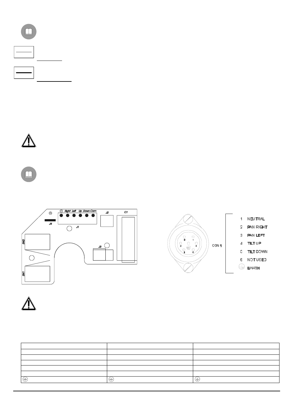
Pan & tilt connection to control units
In the following drawing, identify the terminal block J1 in the horizontal movement circuit for the pan & tilt
connection to the control units:
Pan & tilt connection to DTRX3/DTMRX2 receiver
Fig. 1A
Fig. 1B
WARNING: before the connection, make sure that the output voltage of the receiver corresponds to pan & tilt
voltage (refer to the identification data of the pan & tilt motor and to DTRX3/DTMRX2 manual).
Where to operate: J1 terminal block in the lower printed circuit of the pan & tilt motor (see drawing 1A) or 6+1 poles
connector (see drawing 1B), terminal block of the receiver (see DTRX3/DTMRX2 manual)
Adjustments: connect the terminal block J1 of the pan & tilt motor to that of the receiver according to the following table
Connection to the receiver
Terminal block J1 (Pan & Tilt)
6+1 poles connector
COM
Com
1
DOWN
Down
2
UP
Up
3
RIGH
Right
4
LEFT
Left
5
earth