Connectors and connections – Videotec NXPTH User Manual
Page 19
Pag. 5
MNNXPTH4403
Fig.5
Regulation of the rotating angle of the pan & tilt:
The maximum reachable rotating angle is of about
A=350°. For this reason there is a “dead angle” not
covered from the pan & tilt visible in Fig.5.
If this “dead angle” is inside the desired field of vision
it is necessary to move again the limit switch cams on
the original configuration of Fig.3 and rotate the fixing
position of the pan & tilt on its bracket (see Fig.6).
Then regulate again the rotating angle as described
in Fig.4.
Fig.6
Connectors and connections
The installation must be carried out only by qualified technical staff: an improper connection of the peripheral
units may cause the keyboard to be isolated from the rest of the system.
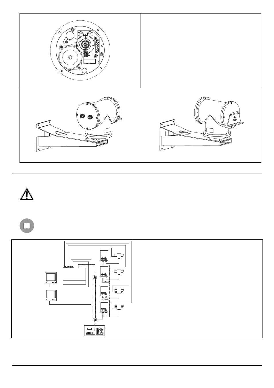
Installation example
One operator with more monitors, who controls a series of pan & tilt motors in cascade configuration.
MATERIAL USED
Control keyboard:
• 1 control keyboard
Video handling:
• 1 video matrix
• 2 monitors
• 4 cameras
• Telemetry handling:
• 4 receivers
• 4 NXPTH pan & tilt motors
Video matrix
Keyboard