Hydraulic generator controller – hgc-2 – High Country Tek HGC-2, Closed Loop Controller User Manual
Page 19
Hydraulic Generator Controller – HGC-2
19
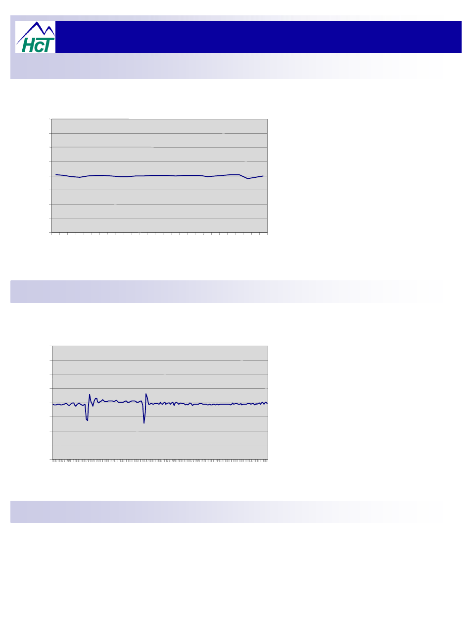
Operational Guide – DC Supply Voltage Fluctuation:
40
45
50
55
60
65
70
75
80
1
3
5
7
9 11 13 15 17 19 21 23 25 27
Fre
q
u
e
n
c
y
-
Hz
DC Supply Voltage Fluctuation
13V
– 10V – 13V within 1 second
The HGC-2 has been designed to work under
extreme conditions seen in mobile equipment.
One variable that can effect operation is the
vehicle battery voltage, but as can be seen in the
graph, right, the fluctuations that can occur have
very little effect on the controlled frequency of the
generator output, with good control being shown
at all times.
Time base = Milliseconds
40
45
50
55
60
65
70
75
80
1 16 31 46 61 76 91 106 121 136 151 166 181
Fre
q
u
e
n
c
y
-
Hz
Prime Mover Speed changes
In the event that the prime mover has variations
in speed ( i.e. engine momentary loading ), the
controller must be able to react quickly and
smoothly, avoiding major over and undershoots
and recovering to steady state as soon as
possible.
This test demonstrates the generator output with
prime mover speed changes from mid range (
normal = 3600RPM ) to minimum ( 3400 RPM )
and then to maximum ( 3800 RPM ).
There are few hydraulic generator specifications existence. The most common is the NFPA specification for generators
applied to fire protection equipment.
It is based on a non-electronically controlled hydraulic generator (load sense pump with fixed orifice) and thus addresses
dynamics specific to that design, such as frequency droop over time under full load (to assess volumetric efficiency
losses). This specification is attached. A generator using either test specimen will meet this specification.
Test Specifications - General
:
Test Specifications – Prime Mover Speed Change
Time base = Milliseconds