Hydraulic fan system controller: hfs – High Country Tek HFS User Manual
Page 24
Hydraulic Fan System Controller: HFS
The HFS controller has been designed to integrate into a typical cooling system and control a hydraulically driven fan
system proportionally or in an ON/OFF manner based on user settings.
There are three (3) independent industry standard two wire thermistor inputs, two (2) fan speed over-ride inputs and
one (1) proportional valve output.
The thermistor inputs can also interface directly with pre-set ON/OFF temperature switches without the finer more
accurate proportional control offered by the thermistors.,
The unit once calibrated and set-up with the supplied software, uses the fan speed to regulate the temperature that
is measured as being the highest above its‟ user selected set point back towards the desired temperature set value.
User settings and adjustments to the regulation process are made via a laptop PC to allow precise customizing the
unit for specific applications.
There are available settings for Minimum and Maximum coil current, Dither frequency and amplitude and ramp up and
down to ensure smooth control of the fan.
Once commissioned, the entire controller „profile‟ can be saved as a file on the PC for backup purposes or serial
production uses as this can be directly uploaded into a new „Blank‟ fan controller unit.
There are no onboard potentiometers or switches for user settings to ensure best controller integrity and operation
under harsh environmental conditions.
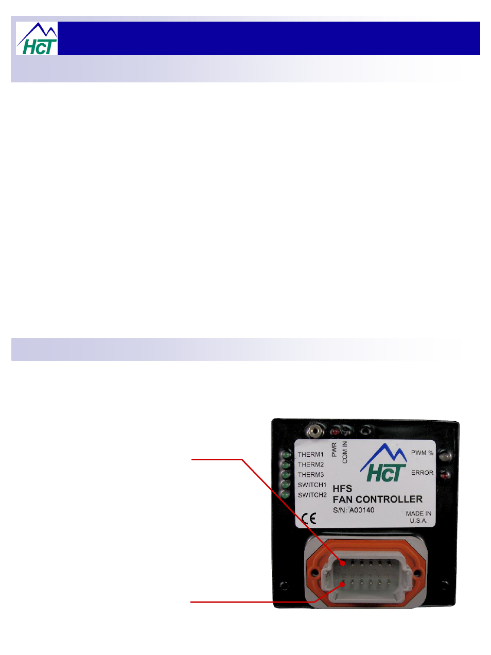
Mating connector Parts:-
Deutsch # DT06-12SA Plug
Deutsch # W12S
– Lock
Deutsch # 0462-201-16141
– Socket pins
Deutsch distributor
– Ladd Industrial sales – 800-223-1236.
Pin 1:-
Thermistor #1 +signal I/P.
Pin 2:-
Thermistor #2 +signal I/P.
Pin 3:-
Thermistor #3 +signal I/P.
Pin 4:-
Over-ride Switch #1 I/P.
Pin 5:-
+8 – 40VDC Power supply Input.
Pin 6:-
+Proportional Valve Output.
Pin 7:-
-Proportional Valve Output.
Pin 8:-
0V Power Supply Input.
Pin 9:-
Over-ride Switch #2 I/P.
Pin 10:-
Thermistor #1 -signal I/P.
Pin 11:-
Thermistor #2 -signal I/P.
Pin 12:-
Thermistor #3 -signal I/P.
Controller Operation:
Connector Information:
24