Chapter 1: description of probe, Data protocol – AMETEK 7100 Leak Detect Stik User Manual
Page 4
2
Chapter 1: Description of Probe
The 7100 liquid level probe uses a proprietary data transmission technique providing a compact information
format for level and temperature data, and a signal pattern which is very easily recognizable at the console.
1.1: Data Protocol
Transmission consists of a sequence of similarly formatted frames of data, each frame in turn, consisting
of 15 pulse pairs and a pause period. The pause period, as well as the 15 pulse pairs, each occupy 1 of 16
equal time slots of approximately 4.5 milliseconds¹.
Time slot #1 is the pause period and carries no signals. This pause is used by the console to synchronize
with the signal sequence. After this pause is found, no further recognition operations are necessary; the
console can simply follow the sequence described below. Each of the remaining 15 time slots carries two
pulses. The time interval between the pulses in each pair is equal to a value of the parameter assigned to the
corresponding time slot. (See Figure 1)
Even numbered pulse pairs #2, 4, 6, 8, 10, 12, 14, & 16 carry temperature related data.
The time interval between the pulses in time slot #3 is proportional to the water level (the lower float position).
The six remaining odd numbered pulse pairs #5, 7, 9, 11, 13, & 15 carry signals related to the product signal.
Thus, information on the product level collected during one frame increases the initial resolution (determined
by the frequency of the clock advancing the high speed counters in the console) by a factor of about 2.5
(square root of 6). See footnote².
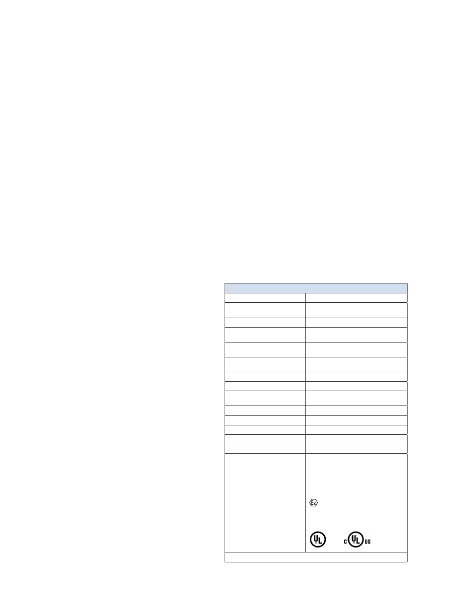
Specifications
Input Voltage
16 to 31 VDC
Sensor Length
Stainless Steel up to 24’
PVDF up to 70’
Enclosure Rating
Material 316 SS or PVDF, IP 68
Typical Level Resolution
(Controller Dependent)
0.010” Inventory Mode
0.001” Leak Detection Mode
Linearity
+/- 0.01% of Full Scale
+/- 0.010”, whichever is greater
Repeatability
+/- 0.001% of Full Scale
+/- 0.00025”, whichever is greater
Temperature Measurement
Up to 5 along the sensor span
Temperature Accuracy, Absolute
+/- 2°F
Typical Temperature Resolution
(Controller Dependent)
+/- 0.01°F
Temperature Sensing Range
- 40°F to +158°F or -40°C to 70°C
Operating Temperature Range
- 40°F to +158°F or -40°C to 70°C
Sensor Output
Pulse Position Modulated
Distance to Monitor
Over 1000’ using twisted pair wire
Floats (not included)
Specs based on 4” standard floats
Approvals
NORTH AMERICA
CLASS I,II,III, DIVISION 1,
GROUPS D,E,F,G: T4 (7100 K&V)
GROUPS C,D,E,F,G,: T4 (7100 M&R)
Exia SECURITE INTRINSEQUE
EUROPEAN UNION IEC
CE 0575
II 1 G
Ex ia IIA T4 Ga (7100 K&V)
Ex ia IIB T4 Ga (7100 M&R)
IECEx UL 11.0041X
DEMKO 09 ATEX 0902049X
LISTED
14X7
Specifications are subject to change without notice. Patented.
The entire message, including time slot #1 through
#16, is referred to as a Frame of data throughout
this document.
NOTE: The first pulse pair in a frame is in
time slot #2 and is hence referred to
as pulse pair #2. As stated above, the
eight even pulse pairs #2, 4, 6, 8, 10,
12, 14, & 16 carry temperature data. #2
through #10 correspond to the lowest to
the highest temperature sensors in the
probe rod, respectively. #12 corresponds
to the temperature sensor in the head
electronics. #14 and #16 are references.
The five sensors are spaced apart equally
in the probe rod. (See Chapter 5 for more
information on computing the temperature).
¹
For probes over 18 feet in length, the frame duration should
be doubled. This is due to the longer wire propagation time.
²
Since the magnetostrictive wire velocity is about 9
microseconds per inch, a 110 MHz. clock would provide a
single level readout resolution of 0.001”. Since the 7100 probe
utilizes the patented resolution-doubling reflection method,
the resolution would be 0.0005”. If a more practical 40 MHz.
clock is used, the resolution is 0.001375”.