Interface hardware – AMETEK 7100 Leak Detect Stik User Manual
Page 12
10
2.1: Interface Hardware
A typical console has the following sub-systems:
1. Probe Mulitplexer
2. Intrinsic Safety Barrier
3. Pulse Discriminator
4. Gate Circuit
5. High Speed Counter
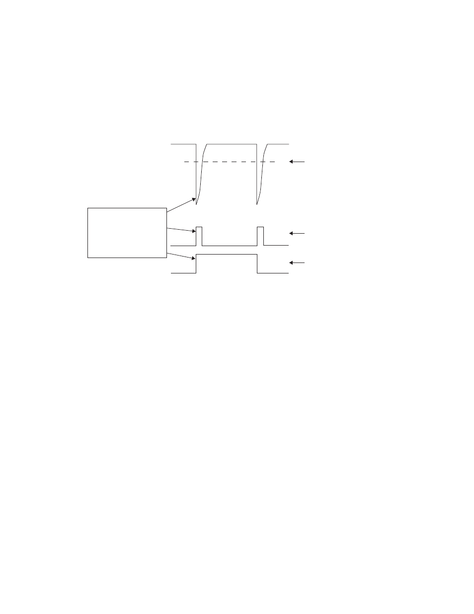
Figure 6: Start and Stop Counters
Gate Signal for
Counters
Comparator
Output
Comparator
Threshold
Use leading edges
of comparator
output to start and
stop counters.
Figure 7 shows typical means of achieving each of these sub-systems. The multiplexing is achieved with the
use of a PNP-style bipolar driver IC. where only one output is turned on at a given time. The output that is
turned on serves two functions; it couples power to the corresponding probe, and it conducts the probes out-
put pulses back to the pulse discriminator.
The intrinsic safety barrier is achieved where the dotted line is shown.
A Stahl Intrinspak 9001/01-280-110-101 could be used as an "off-the-shelf" barrier when installed in accor-
dance per Stahl manual 9001/60/301 and local safety standards. Safety barrier entity parameters must meet
the requirements as called out in installation drawing E0234300.
The pulse discriminator is comprised of a 5:1 pulse transformer that is capacitively coupled to the intrinsi-
cally safe power supply (where the probe pulses are found) and used to invert the pulses, amplify them, and
remove the 24 VDC. offset. Finally, a comparator is used to generate the final output used to drive the gate
circuit. The comparison is done with a nominal threshold voltage of approximately 1 VDC.
The gate and counter circuits are shown only in block diagram form. The clock feeding the counters should be
selected to yield the resolution required (see footnote 2, page 2). The gate circuit should enable the counters
upon the first pulse in a pulse pair and disable the counters on the second after which the counter values are
taken. The gate signal is also used to alert the resident computer that it is time to take the data.
For clock frequencies above 35Mhz., it is recommended that all analog comparators and digital gating circuit
components be relatively high speed. (If FAST or ACT logic is used for the counters, then also use it for the
gating circuits.)